Digital design tools
As a result of advances in technology, it is common practice for digital technology to be used to aid the design, development and manufacturing of components and products. Digital design tools include:
- Used to test a computer aided design (CAD) through computer simulations, providing data to be analysed by designers.
- The process of creating a 2D or 3D design using computer software.
- The manufacture of a part or product from a computer aided design (CAD) using computer-controlled machinery, such as a 3D printer.
A design could start as a set of 2D sketches then evolve into a 3D CAD drawing of the part. Quickly making models, usually by additive manufacturing (building up a 3D model in layers)., eg using 3D printing, can quickly allow it to be tested, evaluated and then finally machined using computer numerical controlled (CNC) machinery, eg a CNC milling machine.
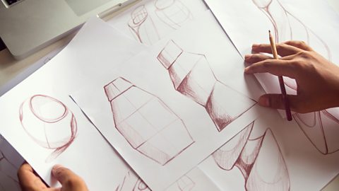
Image caption, Initial sketches
1 of 4
Computer aided engineering (CAE)
Computer aided engineering (CAE) enables a designer to test and analyse the performance of a component or design through the use of computer simulation software. The use of CAE offers greater analytical capabilities in comparison to traditional testing, including:
- decreasing the The time between the start of a project and the final product being manufactured. of a product
- enabling different materials to be tested for suitability
- reducing the cost of development
- decreasing development time as data can be analysed quickly
- allowing improvements to be made quickly as the files are digital
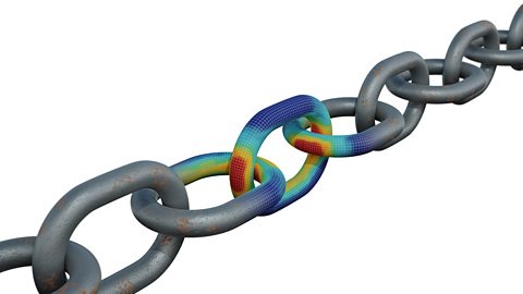
Finite element analysis (FEA)
The use of computer simulation software to virtually test the engineering performance of designs. is the use of computer simulation software to virtually test the engineering performance of designs. This can include simulating how a structure performs under stress or strain or how heat and fluids are transferred in and around designs. An architect may use FEA simulations to test how a bridge would respond to loads being driven across it or the effect of winds blowing over it.
Computational fluid dynamics (CFD)
The use of software to simulate and analyse gas and liquid flow around a design. is the use of software to simulate and analyse gas and liquid flow around a design. For example, an aeronautical (airplane) engineer may use CFD testing to investigate the effects of different wing designs on the performance of an aircraft.
Shape optimisation
Finding an optimal shape for a part or a product. is a method of using computers to help in finding an optimal shape for a part or a product - maintaining its performance while reducing its weight. An example would be removing the excess material from a solid wheel to create spokes.
Computer aided design (CAD)
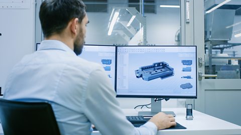
Computer aided design (CAD) software is a common feature of an A cyclic design process of modelling and testing to achieve gradual improvements to the design. process, allowing designers to create designs digitally in either 2D or 3D form. This can then be edited and manipulated quickly and can be exported to be used in computer aided manufacture (CAM).
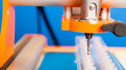
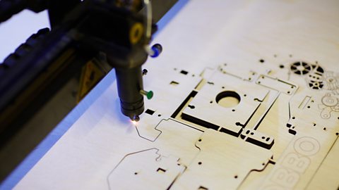
Computer aided manufacture (CAM)
A product can be designed on a computer aided design (CAD) package and then sent to a computer aided manufacture (CAM) machine to be cut out, eg using a laser cutter. This can have a high initial cost so is often used in mass production or to create rapid The first working model of a design used for testing, development and evaluation. at the start of a design process to save time and money.
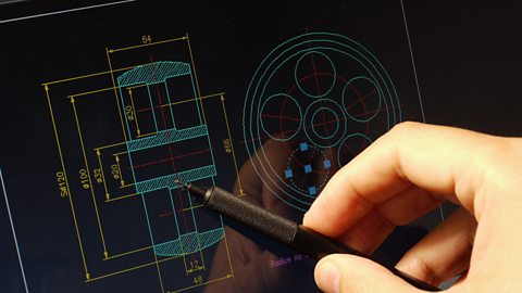
Image caption, Computer aided design (CAD)
1 of 2
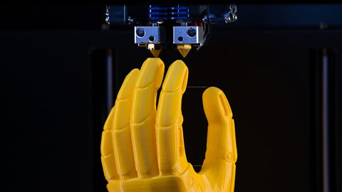
Rapid prototyping
Rapid prototyping is the name given to a family of techniques that allow designers to produce scaled models or full size parts. It is an A method of shaping a form by building on top of material. process, meaning material is added, and a common technique is A method of adding material in layers to build a solid form.. Rapid prototyping is commonly used at the development stage as complex parts can be made quickly.
