Compound gear and pulley systems: Gears
A wheel with teeth that can change the speed of a mechanism. are wheels with Projecting part of a component such as a gear. around the outside. When several wheels are interlocked, they can transfer motion from one place to another, eg in some hand whisks or on bikes.
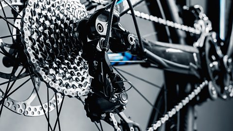
Gears can change the direction or the speed of movement. As there are teeth around the edge of the gears they grip together and so can withstand a greater force, enabling them to move large items such as cars or bicycles.
Gear trains
Two or more gears interlocking together. are when two or more gears are joined together. In a simple gear train, the The starting gear in a gear train that causes all other movement. causes the Transfers motion from the drive gear. to turn in the opposite direction.
Smaller gears with fewer teeth turn faster than larger gears with more teeth. This difference in speed is called the The number of turns the driven gear will make for every turn of the drive gear..
Example
The drive gear has 60 teeth and the driven gear has 15 teeth.
Gear ratio = 15 ÷ 60
= 0.25
For each rotation of the drive gear, the driven gear would rotate four times.
Gear ratio = 1:4
This is known as A gear arrangement where the driven gear rotates more times than the drive gear.. If the drive gear had 15 teeth and the driven gear had 60 teeth, the gear ratio would be 4:1 which is known as A gear arrangement where the driven gear rotates fewer times than the drive gear..
Question
If a cyclist is pedalling with a drive gear of 50 teeth and a driven gear of 25 teeth, what is the gear ratio?
Gear ratio = 50 ÷ 25
= 2
Gear ratio = 2:1
If the drive gear and the driven gear are separated by another gear, called the A gear that can be placed between two other gears to ensure the input and output gears rotate in the same direction., they will move in the same direction.
Pulleys
A wheel with a grooved edge that a cord passes around. use The ratio of force produced compared to force applied., similar to levers, to lift up loads. Pulleys are wheel shaped with a groove that allows a cord to sit inside the groove. They can be used by hand or attached to a motorised A machine that lifts heavy loads by turning a rope or chain around a circular drum. to increase the amount of weight that can be lifted.
Pulleys are a simple and manoeuvrable way to move large objects. They are easy to transport to where they are needed and set up, but they do require somewhere stable to hang.
A single pulley changes the direction of force, making pulling down easier than lifting up. Single pulley systems are demonstrated in cranes, lifting a bucket from a well, raising a flag or adjusting window blinds. Even though there is no actual mechanical advantage with one pulley, it is referred to as having a mechanical advantage of one.
One pulley doesn’t make a mechanical advantage, as the same amount of force is needed. However, if additional pulleys are added, a mechanical advantage is created. Using two pulleys together means you need half the force to lift. This is called a An arrangement of two or more pulleys to make lifting a load easier., and is used to lift large, difficult-shaped objects, such as furniture. Adding more wheels to the block and tackle increases the load it can lift.
Example
The 10 N load below would still require 10 N of force to lift as the extra pulley is not taking any additional strain in weight - the weight is still taken by only one section of rope.
The 10 N load below would require half of the force to lift. There are two sections of rope taking the strain, so 5 N of force would be needed to lift it. The mechanical advantage would be 2.
Question
The pulley system below features 300 N of load and 3 pulleys:
What weight is needed to pull the load?
Three sections of rope are taking the strain of the load.
Weight = 300 ÷ 3
= 100 N
