Key points
- Output devices such as motors, solenoids, bulbs, buzzers, relays, LEDs, and 7-segment displays are used in many electronic circuits.
- Circuit diagrams illustrate how these devices are connected and function within a circuit.
- Relays are electrically operated switches that can control other devices like motors and solenoids using a low-power signal to manage high-power circuits.
- LEDs emit light when current passes through and require a current-limiting resistor for protection. Bulbs contain a filament that glows when current passes through.
- 7-segment displays are used to display numerical information and consist of seven LEDs to form numbers 0-9, often controlled by a decade counter IC for accurate counting and display.
Output devices such as motors, solenoids, bulbs, buzzers, relays, LEDs, and 7-segment displays are used in many electronic circuits. Circuit diagrams illustrate how these devices are connected. Relays are electrically operated switches. Relays can be used to control other devices, such as motors and solenoids.
What are examples of output devices?
Light-emitting diode (LED)
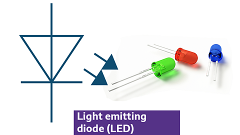
- emits light when current passes through
- polarised component with positive and negative terminals
- needs a current limiting resistor placed in series to the LED for protection
- available in various types and colours
Bulb
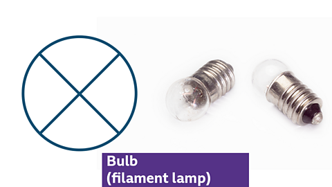
- light source or indicator
- contains a filament that glows when current passes through
- comes in various sizes and shapes
Buzzer
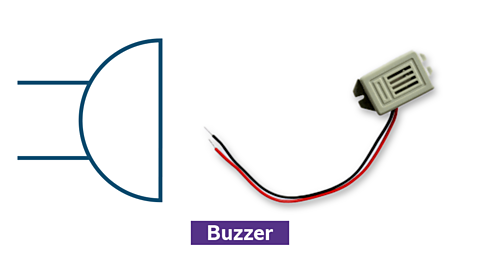
- produces sound or warning signals
- polarised component requiring correct connection
- available in different sizes, shapes, and voltages
Loudspeaker

- converts electrical signals into sound.
- used in devices like radios and alarms.
- vibrates a diaphragm to create sound waves.
Motor

- provides rotary motion
- can move clockwise and anticlockwise
- used to drive mechanisms like conveyor belts and window openers
- used as an output
Solenoid
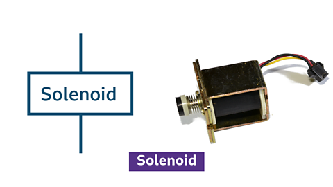
- converts electrical energy into linear motion
- used in locks, valves, and actuators
- moves a metal plunger when current passes through the coil
Relay
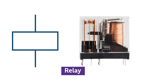
- electrically operated switch
- controls high-power circuits with a low-power signal
- energises a coil to create a magnet to open or close contacts in another circuit
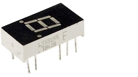
7 Segment display
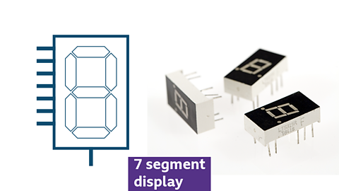
- displays numerical information
- used in digital clocks and calculators
- consists of seven LEDs to form numbers 0-9
- typically, is used with a An integrated circuit (IC) that counts in a series of 10 numbers, from 0 to 9 to help count and display the correct numbers
How to create circuit diagrams containing outputs
High-powered outputs:
Typically, these components need a transistor to amplify the small current used by the circuit to allow them to work properly:
- motor
- solenoid
- relay
- buzzer
Can you describe how the circuit works?
This circuit diagram will typically allow any of these high-powered outputs to operate. You can swap the motor out of this circuit and insert the solenoid, relay or buzzer. You can also swap out the thermistor input for most other switch and sensor types to allow other inputs to trigger the motor.
How the circuit works:
- 5V is being used to power the circuit and it has a SPST toggle switch acting as an on/off switch.
- a thermistor is checking the temperature and has a 10kΩ an electronic component that pulls the voltage in a circuit towards ground, (a common point in a circuit that is used to measure all other voltages). connected A way of connecting components in a circuit. A series circuit has all the components in one loop connected by wires, so there is only one route for current to flow. , creating a a simple circuit that divides a voltage into a smaller one using two resistors.
- the microcontroller has both positive and negative connections for power. It has been programmed to check if the thermistor is above 27 degrees Celsius. If so, it will activate the motor fan to spin to cool the greenhouse down until it reaches 23 degrees Celsius
- when the transistor base leg receives 0.6V from the microcontroller, it will switch on and connect the collector and emitter legs, allowing the motor fan to switch on
- a When voltage is applied across a diode in the opposite direction of its normal current flow, blocking most of the current. diode is placed across the motor (or solenoid/relay) to prevent A spike in voltage generated when the current is interrupted, opposite to the original current, potentially damaging circuitry.
How to use a relay to control a secondary circuit
Using a relay to control a secondary circuit allows a low-power signal to manage a high-power circuit safely and efficiently. Relays act as electrically operated switches, where a small current energises a coil, creating a magnetic field that opens or closes the switch contacts in the secondary circuit.
Can you describe how the circuit works?
- A 5V battery is being used to power the circuit. A SPST (single pole single throw) toggle switch is acting as an on/off switch.
- A push to make switch (PTM) is connected in series to a 10k an electronic component that pulls the voltage in a circuit towards ground, (a common point in a circuit that is used to measure all other voltages)., creating a potential divider into the input of the microcontroller.
- When the PTM is pressed, the microcontroller program will switch on the base leg of the transistor, allowing current to flow through collector to the emitter legs. This will energise the Relay coil.
- When the relay coil is energised, it will make the contacts of the SPST switch on the secondary circuit close, completing the circuit and allowing the 24V lamp to switch on.
How to use a 7-segment display in a circuit
A 7-segment display is used to display numerical information. It consists of seven individual segments (LEDs) arranged in a figure-eight pattern, which can be lit in different combinations to represent numbers from 0 to 9.
If you wanted the number 3 to be displayed, you would need to switch on the following letters of the 7-segment display: A, B, C, D and G.
Although each of the 7 LEDs in the 7-segment display can be individually controlled to make 0-9 appear, it is often better to use a counter IC to act as a driver to control the 7-segment display. The example above uses a 4026B an integrated circuit that counts from 0 to 9 (ten states) before resetting back to 0 that can count from 0-9 and then make the correct pins of the 7-segment display light up to form a number.
Can you describe how the circuit works?
- a 5V battery is being used to power the circuit
a SPST toggle switch is acting as an on/off switch - a push to make switch (PTM) is connected in series to a 10k pull down resistor, creating a potential divider
- when the PTM is pressed, it will make the 4026B counter count once from 0-9 as it receives a pulse on its clock pin.
- the counter will then tell which of the LED segments (a-g) should switch on to display the correct number, for example to display the number it needs segments b and c to light up
- every time the switch is pressed, the counter receives a pulse, and it will count up from 0-9.
When it displays 9, on the next pulse it will go back to display zero.
It is possible to connect more 7-segment displays with 4026B decade counters so that it can display tens and hundreds
Test yourself
More on Electronic and microelectronic control systems
Find out more by working through a topic
- count5 of 13

- count6 of 13
- count7 of 13