What are the types of capactor
A capacitor is an electronic component that stores and releases electrical energy in a circuit. It consists of two conductive plates separated by an insulating material called a dielectric. When a voltage is applied across the plates, an electric field is created, causing the capacitor to store energy.
There are two main types:
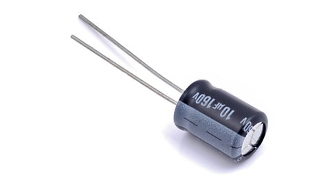
- Electrolytic capacitors – these are polarised, so they have a positive and a negative leg.
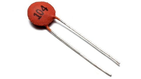
Usage: applications requiring large capacitance values, such as timing circuits and power supplies. - Ceramic capacitors – these are non-polarised.
Usage: applications like signal smoothing.
Circuit symbols
What are capacitors used for?
Choose capacitors based on the required capacitance, voltage rating, and whether the circuit requires a polarised or non-polarised capacitor.
Units of Capacitance:
- Farads (F): The basic unit of capacitance.
For a typical small voltage circuit, a Farad is quite large so Microfarads (µF) or Nanofarads (nF) are more likely to be used. The bigger the value of the capacitor, the longer it takes to charge/discharge! - Microfarads (µF): 1µF = 0.000001F (10⁻⁶)
- Nanofarads (nF): 1nF = 0.000000001F (10⁻⁹)
- Picofarads (pF): 1pF = 0.000000000001F (10⁻¹²)
Examples of capacitors in a circuit
Stage 1: The 9V battery sends electrical charge to the capacitor's plates, allowing it to store energy (like filling a tank). The capacitor continues charging until it's full.
Stage 2: When the A type of electrical switch that allows you to connect a single input to one of two outputs. It has has one input terminal (the pole) and two output terminals (the throws). is manually pressed, the battery is now cut off from the rest of the circuit. However, the stored energy from the capacitor can now flow through the circuit, making the LED light up briefly. The resistor will control the discharge rate of the capacitor by limiting the flow of current through the circuit.
What is Ohm’s law?
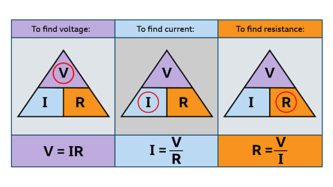
Ohm’s Law describes the relationship between voltage (V), current (Ɪ), and resistance (R) in an electrical circuit.
The law states that:
Voltage = Current × Resistance
or
V=ꞮR
How to use Ohm's law
If you know any two of these quantities, you can calculate the third.
The formula can be rearranged as follows:
Test yourself
More on Electronic and microelectronic control systems
Find out more by working through a topic
- count7 of 13

- count9 of 13