Key points
- resistance measures how much a component opposes the flow of electric current, measured in ohms (Ω)
- resistors are used to control current and protect other components
- colour coding is used to identify resistor values and tolerance (5%, 10%…)
- the total resistance of resistors in series is the sum of individual resistances \((\text R_\text t=\text R_1 +\text R_2 + \text R_3 \dots \text R_\text n)\))
- the total resistance of resistors in parallel is calculated using the formula \(\frac{1}{\text R _\text t}=\frac{1}{\text R_1}+\frac{1}{\text R_2} \dots\) or \(\frac{1}{\text R _\text t}=\frac{\text R_1\times\text R_2}{(\text R_1+ \text R_2)}\)
- E12 & E24 series are standard resistor values to simplify design and manufacturing
- tolerance indicates the acceptable variation in resistor value
- current-limiting resistors are used to protect light emitting diodes (LEDs) from excessive current
How to read a resistor's colour coding system
Each resistor has four coloured bands that represent its value and tolerance:
- First band: represents the first digit
- Second band: represents the second digit
- Third band: multiplier (the number of zeros to add)
- Fourth band: tolerance (accuracy of the resistor)
How to calculate resistance in series
When resistors are connected in components connected end-to-end in a single loop, current flows through each component in turn, their resistances add up. The total resistance (\(\text R_\text t\)) is the sum of all individual resistances (\(\text R_1,\text R_2,\text R_3,\text R_4,\text R_5\) etc): \(\text R_\text t=\text R_1+\text R_2+\text R_\text 3+\text R_4+\text R_5\)…etc
For example, if you have three resistors in series with values of 1kΩ, 2kΩ, and 3kΩ, the total resistance would be: \(\text R_\text t = \text{1kΩ + 2kΩ + 3kΩ = 6kΩ}\)
How to calculate resistance of resistors in parallel
When resistors are connected in multiple routes for current to flow, the voltage is the same across each component of the circuit, the total resistance can be calculated using the formula:
\(\frac{1}{\text{R}_\text{t}}=\frac{\text{R}_1\times{\text{R}_2}}{\text{R}_1 + \text{R}_2}\)
Calculation of the resistance of resistors in parallel:
R₁ = 3.9kΩ
R₂ = 6.8kΩ
\( \begin{eqnarray*}\text{R}_\text{t} &=& \frac{3.9 \times 6.8}{3.9 + 6.8} \\ &=& \frac {26.52}{10.7} \\ &=& 2.48kΩ \end{eqnarray*}\)
What is the tolerance of a resistor
Tolerance indicates how much the actual resistance can vary from the stated value. Common tolerances are 5% (a gold band) and 10% (a silver band). For example, a 1000Ω resistor with a gold band (5% tolerance) can have a resistance anywhere between 950Ω and 1050Ω.
The fourth band colour indicates the tolerance.
To calculate the tolerance range, multiply the resistance value by the tolerance percentage. For the previous example, multiply 1000Ω x 0.05 = 50Ω tolerance range.
Example:
- a resistor has a stated value of 100Ω and a tolerance of 10%
Calculate the tolerance range
- 10% of 100Ω = (10÷100) × 100Ω = 10Ω
Determine the minimum and maximum resistance values:
- minimum resistance = 100Ω - 10Ω = 90Ω
- maximum resistance = 100Ω + 10Ω = 110Ω
The actual resistance of this resistor could be anywhere between 90Ω and 110Ω
What are E12 and E24 series?
The E12 and E24 series are sets of standard resistor values used to simplify the design and manufacturing of electronic circuits.
Not every value for a resistor is available - 22kΩ resistors are easily found while 25kΩ is not, for example. As resistor values increase the difference is smaller and eventually this difference becomes too small to be significant in a circuit.
For example, increasing in values of 10 for resistors at 10, 20, 30… is noticeable, but when you reach 1000: 10010,1020… 10 is very small. To overcome this, as resistor size increases, so does the 'step' or distance between the values of each resistor. Resistor values are chosen so that the ratio between consecutive values is roughly constant. This means the percentage difference between values is similar across the range.
The E12 series uses 12 standard values (10, 12, 15, 18, 22, 27, 33, 39, 47, 56, 68, 82) for each power of ten (10Ω, 100Ω, 1000Ω (1kΩ), etc.) and is typically used for resistors with 10% tolerance. The E24 series has 24 values for each power of ten, allowing for finer adjustments between values.
To protect an LED with a resistor, choose the next larger standard resistor value.
- preferred values ensure that resistors are widely available and consistent, making it easier to design and maintain circuits.
- E12 series resistors typically have a silver fourth band (10% tolerance) and E24 series resistors have a gold fourth band (5% tolerance).
- if you need a resistor value of 34Ω, you can use the E12 and E24 series to get a value close to 34Ω:
- E12 Series: the nearest value available is 33Ω.
- E24 Series: the nearest value available is 33Ω or 36Ω.
Table showing the E12 and E24 series for standard resistor values
| E12 | E24 |
|---|---|
| 10 | 10 |
| 11 | |
| 12 | 12 |
| 13 | |
| 15 | 15 |
| 16 | |
| 18 | 18 |
| 20 | |
| 22 | 22 |
| 24 | |
| 27 | 27 |
| 30 | |
| 33 | 33 |
| 36 | |
| 39 | 39 |
| 43 | |
| 47 | |
| 51 | |
| 56 | |
| 62 | |
| 68 | |
| 75 | |
| 82 | |
| 91 |
How to protect LEDs using resistors
LEDs require current-limiting resistors to prevent them from burning out. The resistor limits the current flowing through the LED. Typical values for current-limiting resistors are - 220Ω, 330Ω and 470Ω.
To calculate the value of a current-limiting resistor, use Ohm’s Law
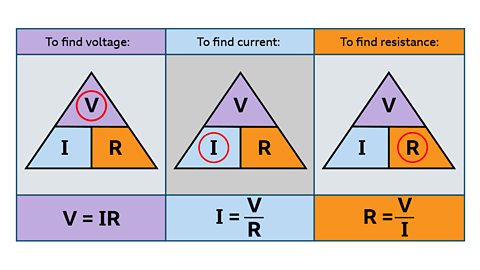
The quantities voltage, current and resistance are linked by the relationship:
Voltage = Current × Resistance
This relationship is called Ohm's Law. We usually write Ohm's Law as;
V=IR
- The symbol for resistance is R, it is measured in ohms (Ω).
- The symbol for voltage is V, it is measured in volts (V).
- The symbol for current is I, it is measured in amperes (amps) (A).
If given any two of these quantities, you will be able to work out the third.
The equation can be rearranged to work out any of the three quantities.
Test yourself
More on Electronic and microelectronic control systems
Find out more by working through a topic
- count9 of 13