Key points
- Understanding DIL ICs means knowing how dual-in-line integrated circuits function and identifying pin one.
- The 555 Timer IC is a versatile IC used for timing, producing astable (continuous pulses) and monostable (single pulse) outputs.
- Astable mode produces continuous pulses and is used in LED flashers, clock circuits, and motor control.
- Monostable mode produces a single pulse when triggered, with the duration controlled by resistor and capacitor values.
- The time constant is the time period for which the output remains high or low, influenced by capacitance and resistance.
- Digital signals and binary involve recognising high (on) and low (off) voltage levels, and understanding binary counting and conversion.
How to use dual-in-line (DIL) integrated circuits
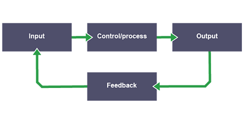
Understanding dual-in-line (DIL) integrated circuits is important for working with electronics. This involves knowing how they function and identifying pin one. The 555 timer IC (integrated circuit) can produce two types of outputs: an electronic circuit that constantly switches between two states, an astable circuit is always changing and an electronic circuit that stays in one stable state, it produces a single pulse and then goes back to its stable state after a short time. It is essential to interpret the output waveforms for these circuits and perform basic calculations for their outputs.

The functions of a 555 timer
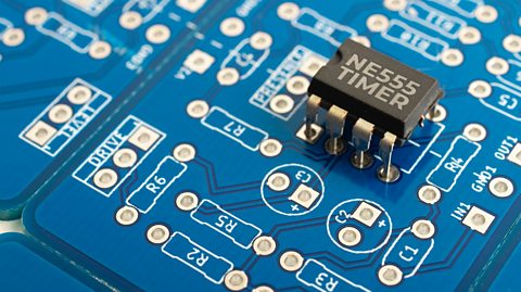
The 555 timer is a versatile integrated circuit (IC) that can control timing in electronic circuits. It's one of the most widely used ICs due to its reliability and flexibility.
This timer can operate in two main modes:
- astable (continuous pulses)
- monostable (single pulse)
Astable Mode:
- produces continuous output pulses
- output switches continuously between high and low
- used for led flashers, clock circuits and motor control
How the 555 astable circuit works:
Describe how the circuit works:
- Set up: The 555 timer IC is set up to continuously switch its output between high (9V) and low (0V) states, creating a repeating cycle (astable). The input connections (Pins 2, 6 and 7) to the 555 timer are key to determine which mode it is in.
- LED Flashing: When the output at pin 3 is low (0V), the top red LED lights up for a time period. But, when the output is high (9V), the bottom blue LED lights up for a time period. This causes the two LEDs to flash alternately.
- Frequency Control: The rate at which the LEDs flash is determined by the values of the resistors (R1, VR1) and the capacitor (C1) in the circuit. The bigger these values are, the longer the LEDs will stay on.
- Protection: The 470Ω resistors ensure that the LEDs receive the correct voltage, protecting them from damage.
555 astable waveforms
- Square wave: alternates between high (on) and low (off) states.
- Sharp transitions: creates clear, rectangular pulses.
- Continuous cycle: repeats the pattern without stopping.
How to calculate the output time of an astable 555 circuit:
\( \text T = \frac{1}{\text f}\)
Where:
- \( \text T\) = time period in seconds (s)
- \(f\) = frequency in Hertz (Hz)
But, to find the frequency for an astable 555 timer another equation is needed:
\(f = \frac{1.44}{(R_1+2R_2)C}\)
Where:
- \(f\) = frequency in Hertz (Hz)
- \(R_1\) = resistance in ohms (Ω) of the top resistor
- \(R_2\) = resistance in ohms (Ω) of the middle resistor (VR1 in the example above)
- \(C\) = capacitance in Farads (F)
Based on the 555 astable LED circuit diagram above:
\(R_1\) = 1kΩ (1,000Ω)
\(R_2\) = 10kΩ (10,000Ω)
\(C\)= 1000μF (0.001F)
\(f = \frac{1.44}{(R_1+2R_2)C}\)
\(f = \frac{1.44}{(1000+20000)\times 0.001}\)
\(f = \frac{1.44}{(21000)\times 0.001}\)
\(f = \frac{1.44}{(21)}\)
\(f = 0.0686 \text {Hz}\)
Now that the frequency has been calculated, the time period can be found:
\( \text T = \frac{1}{\text f}\)
\( \text T = \frac{1}{0.086}\)
\( \text T = 14.58\)
The time for this astable 555 timer to flash/pulse the red LED (low) and then flash the blue LED (high) will take 14.58 seconds
How the 555 monostable circuit works:
- Set up: The 555 timer is set up so that when triggered by the push-to-make switch (PTM), the output (pin 3) goes high (9V) for a set time period, switching on the base leg of the NPN transistor so the buzzer sounds. The input connections (Pins 2, 6, and 7) to the 555 timer are key to determining which mode it is in.
- Triggering the circuit: pressing the PTM switch creates a pulse at pin 2, which triggers the 555 timer to start the time period.
- Buzzer sounding: once triggered, the output at pin 3 goes high, switching on the base leg of the NPN transistor. This allows the current to flow from the collector leg to the emitter leg. The buzzer is now switched on for a time determined by the variable resistor (VR1) and capacitor (C1).
- Adjustable timing: the duration the buzzer stays on can be manually adjusted by changing the value of VR1, by increasing the size of VR1 the buzzer will remain on for longer.
555 monostable waveforms:
- Single pulse: produces one output pulse when triggered.
- High state: pin 3 goes high (on) for a set period.
- Return to low: after the time period, the output returns to low (off).
- Controlled duration: the length of the high state is determined by the resistor (R) and capacitor (C) values.
How to calculate the output time of a monostable 555 circuit:
Time = 1.1 × Capacitor × Resistor
\(\text T = 1.1 \times C \times R\)
Where:
- \(\text T\) = time period in seconds (s)
- \( R\) = resistance in ohms (Ω)
- \( C\) = capacitance in Farads (F)
Based on the 555 monostable alarm circuit diagram above:
\( C\) = 100μF (0.0001F)
\( R\) = 50kΩ (50,000Ω)
\(\text T = 1.1 \times C \times R\)
\(\text T = 1.1 \times 0.0001 \times 50000\)
\(\text T = 5.5\) seconds
When triggered, this monostable 555 timer will turn on the buzzer for 5.5 seconds.
What is the time constant?
In a 555 timer circuit, the time period for which the output remains high or low is influenced by two key components: capacitance (C) and resistance (R). The capacitor stores electrical energy, and the resistor controls the rate at which the capacitor charges or discharges.
The time constant (T) is a measure of how quickly the capacitor charges through the resistor. A larger capacitance or resistance results in a longer time constant, meaning the capacitor takes more time to charge or discharge, thus extending the time period of the timer.
To find the time constant, the formula below is used:
Time Constant T = R × C
Where:
- \(\text T\) = Time constant in seconds
- \(R\) = Resistance in ohms (Ω)
- \(C\) = Capacitance in farads (F)
Example:
- Resistance (\(R\)): 10kΩ (10,000Ω)
- Capacitance (\(C\)): 100µF (0.0001F)
\(\text T = R \times C\)
\(\text T = 10,000\text Ω \times 0.0001\text F\)
The capacitor will take 1 second to charge to about 63% of the supply voltage through the resistor
Digital signals and counting
How to recognise high and low voltage levels
Recognising high and low voltage levels is crucial because it allows us to understand how digital devices process and store information. This binary representation is used in everything from simple logic gates to complex computer systems.
- High voltage (1): represents an ‘on’ state, typically a higher voltage (eg, 9V)
- Low voltage (0): represents an ‘off’ state, typically a lower voltage (eg, 0V)
- Digital signals: use these two states (on/1 and off/0) to perform operations and communicate information
Understanding binary
Understanding binary is essential for working with digital electronics because it is the basis for all computer operations. It helps in designing circuits, programming, and troubleshooting digital devices.
- Binary System: uses base 2, with only two digits (0 and 1)
- Binary counting: is the process of counting in the binary number system. It starts from 0 and increases by 1, just like decimal counting, but only uses the digits 0 and 1.
An example of binary counting:
0 in binary = 0 in decimal
1 in binary = 1 in decimal
10 in binary = 2 in decimal
11 in binary = 3 in decimal
100 in binary = 4 in decimal
101 in binary = 5 in decimal
110 in binary = 6 in decimal, etc.
- Binary addition: similar to decimal addition but only uses 0 and 1.
An example of binary addition:
Add binary numbers 1011 and 1101
1011
+1101
=?
- Rightmost column: 1 + 1 = 10 (write down 0, carry over 1)
- Next column: 1 + 0 + 1 (carry) = 10 (write down 0, carry over 1)
- Next column: 0 + 1 + 1 (carry) = 10 (write down 0, carry over 1)
- Leftmost column: 1 + 1 + 1 (carry) = 11 (write down 1, carry over 1)
1011
+1101
=11000
Therefore, 1011 (binary) + 1101 (binary) = 11000 (binary).
Converting between decimal and binary numbers
- Decimal to binary: divide the decimal number by 2, record the remainder, and repeat until you reach 0. The binary number is the remainders read in reverse order.
Example:
Decimal 10 to binary
- 10 ÷ 2 = 5 (remainder 0)
- 5 ÷ 2 = 2 (remainder 1)
- 2 ÷ 2 = 1 (remainder 0)
- 1 ÷ 2 = 0 (remainder 1)
Binary = 1010
- Binary to decimal: each digit represents a power of 2, starting from the right (e.g., 1, 2, 4, 8, 16, etc.)
Example:
Binary 1011 to decimal:
- Rightmost bit (1): (2⁰ = 1)
- Next bit (1): (2¹ = 2)
- Next bit (0): (2² = 4) (ignored because the bit is 0)
- Leftmost bit (1): (2³ = 8)
- Total value: (8 + 0 + 2 + 1 = 11)
- The binary number 1011 equals the decimal number 11
Test yourself
More on Electronic and microelectronic control systems
Find out more by working through a topic
- count13 of 13

- count1 of 13
- count2 of 13