Key points
- Flowcharts use symbols like 'start', 'stop', 'decision', 'compare', and 'macro' to visually represent program logic.
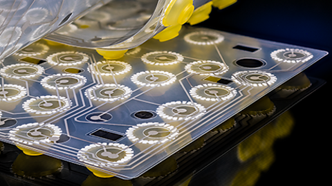
- Microcontrollers (PICs) are compact ICs that control inputs and outputs, used in various applications including robotics.
- Bit patterns in flowcharts represent the binary states of input and output devices, showing how microcontrollers interact with the system.
- Flowcharts help design and explain microcontroller programs, illustrating the sequence of operations and decision points.
- Amplification, using transistors, is required when output devices need more power than a microcontroller can provide.
- Microcontrollers are used in circuits with digital inputs and outputs, and these circuits can be designed and interpreted using flowcharts and bit patterns.
Flowcharts, PICs and bit patterns
Drawing and analysing flowchart diagrams involves elements like count, compare, macro, do macro, end, increments, decrements, and expressions. Microcontrollers (PICs) are used in control systems, identified by their circuit symbols, and applied in robotic control.
Bit patterns show the states of input and output devices. Circuits with digital inputs and outputs are designed and interpreted, and amplification is needed to drive certain output devices from a PIC.
Useful flowchart symbols

Start
- start is a cell that indicates the beginning of the flowchart program
- is needed start the program

Stop
- stop is a cell that signifies the end of the flowchart
- if used, the circuit would need reset to allow the program to restart again

Output
- output is a cell that sends a signal to an output device to tell it to turn on or off
- activates devices like LEDs, buzzers, or motors

Wait
- wait is a cell that pauses the program for a specified amount of time
- delays actions to allow for timing control

Decision
- decision is a cell that makes a choice based on a condition
- directs the flowchart to different paths based on true or false conditions
- example: has a push to make (PTM) switch been pressed? Yes or no?

Compare
- compare is a cell that checks if a specific condition is met by comparing two values
- directs the flowchart based on whether the condition is true or false
- example: is the temperature being read by a thermistor above 27 degrees Celsius?

Macro
- macro is a set of instructions grouped together to perform a specific task
- simplifies the flowchart by grouping complex sequences into a sub-routine
- the macro is activated by running the do macro command in the main flowchart

Do macro
- do macro is a cell that executes the instructions defined in a macro cell
- allows the flowchart to perform grouped tasks as needed
- allows the grouped instructions in a macro to be repeated whenever needed in the main flowchart

End
- end macro is a cell that signifies the termination of the macro sub-routine running
- indicates that the process has completed all necessary actions and should return to follow the main flowchart

Count
- count is a cell that keeps track of the number of times an event occurs
- increments a counter each time the event happens
- could be used by a sensor to detect items going past on a conveyor belt

Increment
- increment is a cell that increases the value of a variable by a set amount

Decrement
- decrement is a cell that decreases the value of a variable by a set amount

Expression
- expression is a cell that performs mathematical or logical operations on variables
- calculates values or evaluates conditions within the flowchart
- can be used with devices requiring calculated inputs, like variable resistors or digital displays
Example flowchart for a simple pedestrian crossing:
Starts the flowchart.
Checks the pedestrian crossing switch to stop the cars. If pressed, red light is on for 15 seconds and checks again for switch
If the switch is not pressed, run amber flash macro five times.
Turn on the green LED for 60 seconds
Check if pedestrian crossing switch pressed, if not loop to keep green LED on for another 60 seconds.
If pressed, switch amber LED on for 3 seconds
Loop back to switch on the red LED for 15 seconds.
Amber flash macro
- Macro to run amber flash sub-routine
- Switch on amber LED
- Wait 05 seconds
- Switch off amber LED
- Wait 05 seconds
- End amber flash macro
Microcontrollers
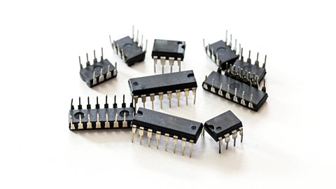
A microcontroller is a low power (5V), compact integrated circuit (IC) designed to run a program to control a range of inputs and outputs. It combines memory, processing units, and input/output interfaces in one chip.
Uses: microcontrollers can be used for various applications, such as household appliances, alarm systems, medical devices, vehicle systems, and electronic instruments.
Sizes: microcontrollers are available in different sizes, including 8-pin, 14-pin, 18-pin, 20-pin and 28-pin versions. The size determines the number of input/output connections and the complexity of tasks it can handle.
Robotic control: in robotics, microcontrollers process sensor inputs and control actuators, enabling robots to perform tasks autonomously. They are crucial for the precise control and coordination of robotic movements.
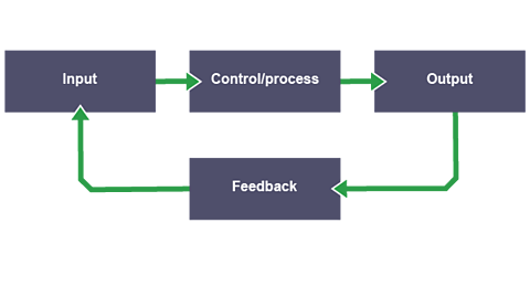
Flowcharts: flowcharts are used to design and explain the sequence of operations in a microcontroller program. They help visualize the steps and decision points in the control process.
Other programming methods are available such as text-based programming languages (BASIC, C++ etc) or simple block-based programming editors.
Bit patterns: bit patterns in a flowchart program represent the states of input and output devices using binary (1/on or 0/off), showing how the microcontroller interacts with other components in the system by switching them on or off at particular stages.
Bit patterns:
1 = ON
0 = OFF
x = Ignore/no change
Can you describe how the circuit works?
How the circuit works:
- the circuit has a push-to-make switch (PTM) as its INPUT, an 8-pin microcontroller as its CONTROL and three LEDs as its OUTPUTS
- the circuit is powered by a 5V battery, as this is the low voltage that the microcontroller needs to operate. A SPST toggle switch is used as a simple on/off switch to the 5V battery
- the PTM switch has a 10kΩ resistor connected in series to create a potential divider to the input side of the microcontroller
- the microcontroller has three outputs to control different coloured LEDs Each LED has its own 330Ω protective resistor connected to it in series
- when the circuit is switched on via the on/off SPST (single-pole single-throw) toggle switch, the flowchart program starts
- the flowchart switches off all three LEDs and then waits until the PTM switch is pressed
- once the PTM switch is pressed, the amber and green LEDs will switch on
- the flowchart then loops to check if the PTM switch is still pressed, and if so, keep the amber and green LEDs illuminated
- if the PTM switch is released, then the LEDs are switched off again
Amplification
Some output devices require more power than the 5V a microcontroller can provide
Examples include:
- motors
- relays
- solenoids
- buzzers
Amplifiers, such as NPN transistors, are used to boost the signal from the microcontroller to drive these high-power devices effectively. In the circuit diagram below, a transistor is being used to amplify the signal coming from the microcontroller to make the relay energise so that it can switch on the secondary 24V lamp circuit.
Can you describe how the circuit works?
How the circuit works:
- a 5V battery is being used to power the circuit. A SPST toggle switch is acting as an on/off switch
- a push to make switch (PTM) is connected in series to a 10k an electronic component that pulls the voltage in a circuit towards ground, (a common point in a circuit that is used to measure all other voltages)., creating a a simple circuit that divides a voltage into a smaller one using two resistors. into the input of the microcontroller
- when the PTM is pressed, the microcontroller program will switch on the base leg of the transistor, allowing current to flow through collector to the emitter legs. This will energise the A type of switch that when energized creates a magnetic field to switch the relay's contacts, controlling the flow of electricity in a circuit.
- when the relay coil is energised, it will make the contacts of the SPST switch on the secondary circuit close, completing the circuit and allowing the 24V lamp to switch on
- a diode is placed in When voltage is applied across a diode in the opposite direction of its normal current flow, blocking most of the current. across the relay coil to stop A spike in voltage generated when the current is interrupted, opposite to the original current, potentially damaging circuitry.. The diode provides a safe path for this reverse current to flow back through the coil, protecting the transistor from damage
Test yourself
More on Electronic and microelectronic control systems
Find out more by working through a topic
- count13 of 13

- count1 of 13
- count2 of 13
- count3 of 13