Key points
- Current is electron flow, measured in amps (A) or milliamps (mA). Use an ammeter in series.
- Voltage is the pushing force, measured in volts (V) or millivolts (mV). Use a voltmeter in parallel.
- Resistance restricts current, measured in ohms (Ω), kilohms (kΩ), or megaohms (MΩ). Use an ohmmeter/multimeter.
- Ohm's law is V=ꞮR (Voltage = Current × Resistance).
- Multimeters measure V, Ɪ, R. Connect for voltage (parallel), current (series), resistance (circuit off). Start high, work down.
Understanding units
Current (flow of electrons)
Amp (A) = big current (like in a kettle)
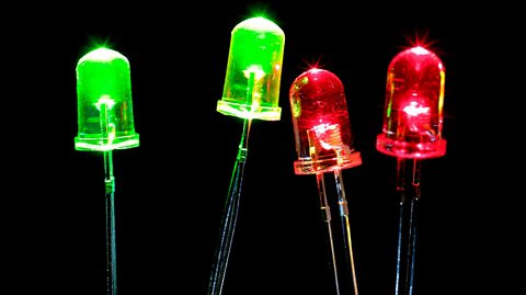
Milliamp (mA) = tiny current (like in LED)
1000mA = 1A
Measurement Tool: Ammeter, connected in series with the circuit.Voltage (pushing force)
Volt (V) = normal battery voltage (like 9V battery)
Millivolt (mV) = tiny voltage
1000mV = 1V
Measurement Tool: Voltmeter, connected in parallel with the component.Resistance (restricts flow)
Ohm (Ω) = small resistance
Kilohm (kΩ) = thousand ohms
Megaohm (MΩ) = million ohms
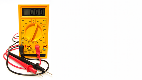
Measurement Tool: Ohmmeter or multimeter.
How to use a multimeter.
- Measuring voltage:
- DC voltage: set the multimeter to the DC voltage (DCV) setting.
- connection: connect the black probe to the COM port and the red probe to the VΩ port, place the probes across the component or section of the circuit where you want to measure the voltage
- reading: read the voltage value displayed on the multimeter
- Measuring current:
- DC current: set the multimeter to the DC current (DCA) setting
- connection: connect the black probe to the COM port and the red probe to the A port, break the circuit and connect the multimeter in series so that the current flows through the multimeter
- reading: read the current value displayed on the multimeter
- Measuring resistance:
- resistance: set the multimeter to the resistance (Ω) setting
- connection: connect the black probe to the COM port and the red probe to the VΩ port, place the probes across the component whose resistance you want to measure, ensure the circuit is powered off
- reading: read the resistance value displayed on the multimeter
SAFETY TIP
Always start on highest setting range and work down to protect the multimeter!
Calculating Expected Values
Using Ohm’s Law (V=ꞮR), you can calculate the expected values for voltage, current, and resistance in a circuit.
What is Ohm’s law?
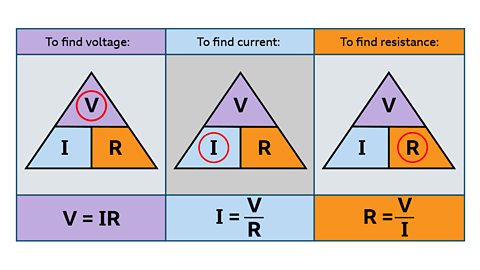
Ohm’s Law describes the relationship between voltage (V), current (Ɪ), and resistance (R) in an electrical circuit.
The law states that:
Voltage = Current × Resistance
or
V=ꞮR
If you know any two of these quantities, you can calculate the third.
The formula can be rearranged as follows:
To find voltage:
Voltage = ?Resistance = 4ΩCurrent = 3A
V=ꞮR
To find current:
Current = ?Voltage = 9VResistance = 180Ω
Ɪ=V/R
To find resistance:
Resistance = ?Voltage = 6VCurrent = 4mA
R=V/Ɪ
Test yourself
More on Electronic and microelectronic control systems
Find out more by working through a topic
- count6 of 13
- count7 of 13

- count9 of 13