2D and 3D drawing techniques
A 3D representation of a design with no vanishing points. and A 2D drawing that looks like a 3D object. are commonly used in technical drawing to show an item in 3D on a 2D page.
Perspective
Perspective drawings show an object in 3D getting smaller in the distance.
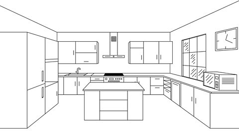
Uses one vanishing point to create a 3D drawing. - This shows an object from the front in a realistic way as it gets smaller going into the distance. The front view goes back towards a The point at which parallel lines meet in the distance., which is a point on the horizon line that all lines meet at.
Uses two vanishing points to create a 3D drawing. - This shows an object from the side with two vanishing points. It gives the most realistic view of a product as it shows the item edge on, as we would see it. It is often used to produce realistic drawings of an object.
Single-point perspective is often used by A professional who specialises in the design of room layout. to show a view into a room, whereas two-point perspective is often used by A professional who specialises in the design of buildings. to show realistic building ideas.

Isometric
Isometric drawings, sometimes called isometric projections, are a good way of showing measurements and how components fit together. Unlike perspective drawings, they don’t get smaller as the lines go into the distance.
There are three main rules to isometric drawing:
- Parallel to the ground. edges are drawn at 30 degrees
- At right angles to the ground or horizontal. edges are drawn as vertical lines
- Straight lines are parallel if they are always the same distance apart. Parallel lines never meet, no matter how far they are extended. edges appear as parallel lines
Isometric drawings are used to show a graphical representation of a 3D object. They are used by architects and engineers to communicate their ideas to the client and manufacturer, showing the product or design Having a fixed relationship to the actual dimensions of an object. The relationship is usually stated as a ratio, eg. 25:1..
Example
Below are two cubes drawn in isometric:
= 30 ÷ 60
= 0.5
This means the second cube has been drawn to half scale, also written as 1:2.
Question
Work out the scale factor of the smaller cuboid below:
Scale factor = 30 ÷ 40 or 60 ÷ 80
= 0.75
Also represented as a factor 3⁄4 or a ratio 3:4.
