Reflection of light
Vibrations that transfer energy from place to place without the transference of matter. - including sound and light - can be reflected at the boundary between two different materials. The reflection of sound causes echoes.
The law of reflection states that the Angle between the incident ray and the normal (the imaginary line drawn at 90 degrees to the reflecting surface). is equal to the The angle between the reflected ray and the normal (the imaginary line drawn at 90 degrees to the reflecting surface).:
angle of incidence = angle of reflection
For example, if a light ray hits a surface at 32°, it will be reflected at 32°.
The angles of incidence and angle of reflection are measured between the light ray and the An imaginary but useful line at right angles to the boundary between air/glass. All angles are measured to this line. - an imaginary line at 90° to the surface. The diagram shows a light ray being reflected at a A flat, two-dimensional surface. mirror.
The image in a mirror is:
upright
virtual
the same size
the same distance from the mirror
In a An image from which rays of light appear to come but do not do so in reality., the rays appear to diverge from behind the mirror, so the image appears to come from behind the mirror.
Extended syllabus content: Measuring and calculating reflection by plane mirrors
If you are studying the Extended syllabus, you will also need to know how to measure and calculate reflection by plane mirrors. Click 'show more' for this content:
Ray diagrams
A ray diagram shows how light travels, including what happens when it reaches a surface.
In a ray diagram, you draw each ray as:
a straight line;
with an arrowhead pointing in the direction that the light travels.
Remember to use a ruler and a sharp pencil.
Investigating the law of reflection
On a sheet of white paper draw a pencil line – label this AB.
Using a protractor, draw a normal at C, roughly the middle of AB.
Draw a line at 20° to the normal.
Position a plane mirror carefully along AB.
Direct a ray of light from a ray box along the 20° line – this is the incident ray. Record the angle of incidence (i) in a suitable table.
Use 2 pencil Xs to mark the position of the reflected ray.
Take away the mirror and join these Xs back to C. This is the reflected ray. Put an arrow on it to show its direction.
Measure the angle between the normal and the reflected ray with the protractor and record the angle of reflection in the table.
Repeat the experiment for a series of incident rays.
Results
| Angle of incidence in ° | Angle of reflection in ° |
|---|---|
| 20 | |
| 30 | |
| 40 | |
| 50 | |
| 60 | |
| 70 | |
| 80 |
Conclusion
When light is reflected by a plane mirror:
the angle of incidence = the angle of reflection.
Refraction of light
Different materials have different densities. Light waves may change direction at the boundary between two transparent materials.
Process by which a wave changes speed and sometimes direction upon entering a denser or less dense medium, eg a light ray changes direction when refracted by a lens. is the change in direction of a wave at such a boundary.
To show the refraction of a wave at a boundary, you need to be able to draw Diagram that represents the direction and angle of travel of light..
Refraction can cause optical illusions as the light waves appear to come from a different position to their actual source.
Explaining refraction
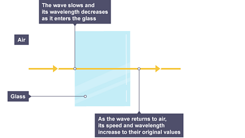
The A measure of compactness and the ratio of mass to volume. It is usually measured in kilograms per metre cubed (kg/m³) or grams per centimetre cubed (g/cm³). of a material affects the speed that a wave will be A wave is passed across or through a material (medium), eg light waves are transmitted through air, glass and water. through it. In general, the denser the transparent material, the more slowly light travels through it.
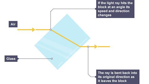
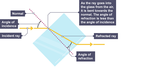
Glass is denser than air, so a light ray passing from air into glass slows down. If the ray meets the boundary at an angle to the An imaginary but useful line at right angles to the boundary between air/glass. All angles are measured to this line., it bends towards the normal.
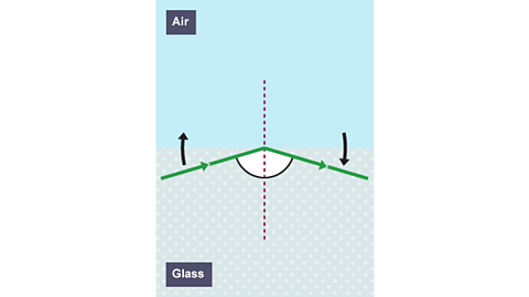
The reverse is also true. A light ray speeds up as it passes from glass into air and bends away from the normal by the same angle.
1 of 3
Key fact: a useful way of remembering the speed and direction changes of light during refraction is:
‘FAST’: Faster - Away / Slower - Towards.
Practical experiment: Investigating the refraction of light
The aim of this experiment is to investigate:
the reflection of light through different types of surfaces
the refraction of light through different substances
Method
Set up a ray box, slit and lens so that a narrow ray of light is produced.
Place a 30 centimetre (cm) ruler near the middle of a piece of plain A3 paper. Draw a straight line parallel to its longer sides. Use a protractor to draw a second line at right angles to this line. Label this line with an ‘N’ for ‘normal’.
Place the longest side of a rectangular A type of transparent plastic. block against the first line. With the normal near the middle of the block, carefully draw around the block without moving it.
Use the ray box to shine a ray of light at the point where the normal meets the block. This is the Light ray moving towards a surface or boundary..
The angle between the normal and the incident ray is called the Angle between the incident ray and the normal (the imaginary line drawn at 90 degrees to the reflecting surface).. Move the ray box or paper to change the angle of incidence. The aim is to see a clear ray reflected from the surface of the block and another clear ray leaving the opposite face of the block.
Using a pencil on the paper, mark the path of:
the incident ray with a cross
the Light ray leaving a surface or boundary. with a cross
the ray that leaves the block with two crosses - one near the block and the other further away
Remove the block. Join the crosses to show the paths of the light rays.
Repeat steps 2 to 7 for a rectangular glass block.
Measure the angle of incidence, angle of refraction and angle of reflection for each block.
Results
Record the results in a suitable table.
The results for a polymer block:
| Angle of incidence (°) | Angle of reflection (°) | Angle of refraction (°) |
|---|---|---|
| … | … | … |
| … | … | … |
The results for a glass block:
| Angle of incidence (°) | Angle of reflection (°) | Angle of refraction (°) |
|---|---|---|
| … | … | … |
| … | … | … |
Analysis
Compare the angle of incidence with the angle of reflection for each block.
Compare the angle of incidence with the angle of refraction for each block.
Evaluation
The light rays should obey the law of reflection. To what extent do the results show this?
Risks/hazards
| Hazard | Consequence | Control measures |
|---|---|---|
| Ray box gets hot | Minor burns | Do not touch the bulb and allow time for it to cool |
| Semi-dark environment | Increased trip hazard | Ensure the environment is clear of potential trip hazards before lowering the lights |
Video: Refraction of light
In this video, science presenter Jon Chase explains the refraction of light. He demonstrates how refraction can make the handle of a Pyrex jug seemingly disappear.
Narrator: More magic now – making the handle of a Pyrex kitchen jug disappear.
You never know – might come in handy some day… maybe!
The power of invisibility – it's not just the stuff of science fiction and superheroes.
It's a reality! This is the handle of a Pyrex jug. It's perfectly visible, right?
But watch what happens when I add some vegetable oil…
Woah! The handle's disappeared!
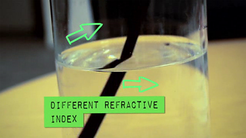
The reason this happens is because light refracts.
Light moves at different speeds through different substances, and this speed is measured by something called refractive index.
When light travels through two substances, with different refractive indexes, it changes direction at the boundary between the two substances, if it's travelling at an angle.
This can be seen here by shining a light through a glass block. This change in direction is called refraction.
Refraction makes looking at objects under water quite tricky, since water and air have different refractive indexes.
The light from objects under water changes direction when it leaves the water, making them appear in a different place to where they actually are.
Diving birds have to make this adjustment when looking for fish.
An object is only visible if it reflects or refracts light.
When the glass is empty, the handle of the jug is visible because the air in the glass has a different refractive index to the Pyrex.
But the vegetable oil has a similar refractive index to the Pyrex.
When we add oil to the glass, the light leaving the handle no longer refracts, and hey presto – the handle disappears!
Refraction by a prism
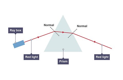
The incident ray is refracted towards the normal as it enters the glass prism from air.
It is then refracted away from the normal at the boundary between glass and air as it leaves the prism.
Internal reflection
When a ray of light exits a material, some of it can be reflected back into it. This is called internal reflection. Mirrored sunglasses reflect some of the light back to allow you to see your reflection in them but allow some light to pass through or the person wearing them could not see.
Total internal reflection
When light passes from one A material through which a wave can be transmitted (propagate). to another, it changes speed. This is because the speed of a wave is determined by the medium through which it is passing.
When light speeds up as it passes from one material to another, the angle of refraction is bigger than the angle of incidence.
For example, this happens when light passes from water to air or from glass to water.
The diagram above shows light incident on a water-air interface.
- angle of incidence is the angle between an incident ray and the normal
- angle of refraction is the angle between a refracted ray and the normal
When the angle of refraction is equal to 90°, the angle of incidence is called the critical angle.
The angle of refraction cannot be greater than 90°. Look at the two images in the slideshow below to see what happens as the angle of incidence increases.
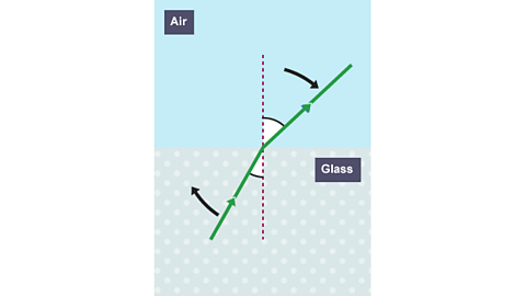
Image caption, Angle of incidence less than critical angle
As the angle of incidence increases, the angle of refraction gets closer to ninety degrees.
1 of 2
At any angle of incidence greater than the critical angle, the light cannot pass through the surface - it is all reflected.
This is called total internal reflection.
total because all of the energy is reflected
internal because the energy stays inside the material
reflection because the light is reflected
If the angle of incidence is increased further, so that it is greater than the critical angle, the light will be totally internally reflected.
The conditions required for total internal reflection (TIR) to occur are:
the light must be travelling from a more dense medium into a less dense medium (i.e. glass to air)
the angle of incidence must be greater than the critical angle
Extended syllabus content: Critical angle equation
If you are studying the Extended syllabus, you will also need to know the critical angle equation. Click 'show more' for this content:
The relationship between critical angle, \({c}\), and refractive index, \(n\) is \(sin\) \({c}=\frac{1}{n}\)
Question
Calculate the critical angle for red light incident on a water-air interface.
The refractive index of water is \(1.33\) for this colour of light.
Answer
\(n= 1.33\)
\(sin\) \({c}=\frac{1}{n}\)
\(sin\) \({c}= \frac{1}{1.33}\)
\({c}=48.7535^\circ\)
Critical angle of water for this light \(=48.8^\circ\)
This can be rearranged to find the refractive index:
\(n = \frac{1}{sin~c}\)
A substance with a high refractive index, like diamond, will have a low critical angle.
Extended syllabus content: Refractive index
If you are studying the Extended syllabus, you will also need to know about refractive index. Click 'show more' for this content:
Refractive index
The speed of light is determined by the medium (material) through which the light is travelling. Light travels faster in a vacuum than it does in any other medium.
Light changes speed as it passes from one medium to another. This is called refraction.
The frequency of light does not change as it refracts.
The refractive index of a material is a measure of the change in the speed of light as it passes from a vacuum (or air as an approximation) into the material.
\(n=\frac{v_{1}}{v_{2}}\)
In the equation above:
\(n\) is the refractive index of the material
\(v_{1}\) is the speed of light in a vacuum
\(v_{2}\) is the speed of light in a material
The bigger the refractive index, the slower the light travels in that material - ie the smaller \(v_{2}\) is.
Question
Light of frequency \(4.6\times 10^{14}Hz\) travels at a speed of \(1.24\times 10^{8}ms^{-1}\) in diamond.
Calculate the refractive index of diamond for this colour of light.
\(v_{diamond}=1.24\times 10^{8}ms^{-1}\)
\(c=3.0\times 10^{8}ms^{-1}\)
\(n=\frac{v_{1}}{v_{2}}\)
\(n_{diamond}=\frac{3\times 10^{8}}{1.24\times 10^{8}}\)
\(n_{diamond}=2.42\)
Refractive index of diamond for this colour of light \(=2.42\)
Now state the frequency of this light in air.
The frequency of this light in air \(=4.6\times 10^{14}Hz\). (Frequency does not change when light passes from one material to another)
Extended syllabus content: Refraction and angle of incidence
If you are studying the Extended syllabus, you will also need to know about refraction and angle of incidence. Click 'show more' for this content:
Refraction and angle of incidence
When a ray of light is incident at normal incidence, (at right angles), to the surface between two optical materials, the ray travels in a straight line.
When the ray is incident at any other angle, the ray changes direction as it refracts.
The dotted line is the normal (perpendicular) to the surface. In refraction calculations, angles are always measured between rays and the normal.
The change in direction of a ray depends on the change in the speed of the light and can be used to calculate the refractive index.
For the example above the refractive index \(n\) of the glass is given by \(n=\frac{sin\theta _{i}}{sin\theta _{r}}\)
When you use this relationship, angle \(\theta _{i}\) must always be the angle in a vacuum (or air).
Refractive index depends on the frequency or colour of light. Light of higher frequency has a greater refractive index than lower frequency light. This explains why a prism can disperse white light into different colours.
The change in refraction is quite small and is only significant for some geometries.
Question
A ray of light is incident on the surface of water as shown in the diagram.
State whether the light travels faster in air or water.
The light travels faster in air as the angle of incidence \(50^\circ\) is greater than the angle of refraction \(\theta\).
Question
Now calculate the angle of refraction of the ray.
We know that:
\(\theta _{i}=50^\circ\)
\(n_{water} = 1.33\)
And:
\(n=\frac{sin\theta _{i}}{sin\theta _{r}}\)
\(1.33=\frac{sin50^\circ}{sin\theta}\)
Therefore \(\sin \theta =0.5759732\)
\(\theta =35.1678\)
Angle of refraction \(=35^\circ\)
Extended syllabus content: Optical fibres
If you are studying the Extended syllabus, you will also need to know about the use of optical fibres. Click 'show more' for this content:
Applications of total internal reflection
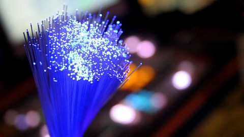
Optical fibres
Total internal reflection allows light to be contained and guided along very thin fibres.
Usually made of glass, these are called optical fibres and they have many uses:
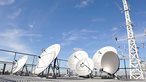
fibre broadband internet sends computer information coded as pulses of light along underground optical fibres;
doctors can look at the inside of their patients using an endoscope - a long tube which guides light into the patient and then guides the reflected light back out to give an image;
decorations, such as some artificial Christmas trees, carry coloured light to different parts of the decoration and let it shine out in different directions.
An optical fibre is a thin fibre of high-quality glass.
Very little light is absorbed by the glass.
Light getting in at one end undergoes repeated total internal reflection and is trapped inside the glass, even when the fibre is bent. It emerges at the other end only slightly less bright.
Information such as computer data, telephone calls and video signals can be converted into either visible light pulses or infrared pulses, and transmitted long distances by optical fibres.
This enables long distance communications to occur quickly and cheaply – a glass fibre is much cheaper than a copper wire needed to carry electrical signals.
In addition, optical fibres can carry much more information than a copper cable of the same diameter.
Endoscopes
Optical fibres are also used in endoscopes that allow surgeons to see inside their patients.
A bundle of optical fibres in a tube guides light into the patient and then guides the reflected light back out to give an image.
A surgeon can see on a monitor what is happening inside a patient’s body, in real time.
Optical fibres make keyhole surgery possible because the endoscope also has instruments for cutting and retrieving tissue.
This means the patient doesn’t have to be cut open which reduces scaring and makes recovery quicker and less painful.
Thin lenses
A lens is a shaped piece of transparent glass or plastic that refracts light. When light is refracted, it changes direction due to the change in density as it moves between air and glass or plastic. Lenses are used in cameras, telescopes, binoculars, microscopes and corrective glasses. A lens can be An object or shape that curves or bulges outwards, like a circle or sphere. (also called 'converging') or Curving inwards, rather than bulging outwards (also called 'diverging').
Convex lenses
A convex (converging) lens is thicker in the middle than it is at the edges. Parallel light rays that enter the lens Move towards each other.. They come together at a point called the Also known as 'focal point'. The focus of a lens where light rays appear to converge or to diverge from..
In a ray diagram, a convex (converging) lens is drawn as a vertical line with outward facing arrows to indicate the shape of the lens. The distance from the lens to the principal focus is called the The distance between the centre of the lens and the focal point..
Concave (diverging) lenses
A concave (diverging) lens is thinner in the middle than it is at the edges. This causes parallel rays to When a light ray splits up or spreads out.. They separate but appear to come from a principal focus on the other side of the lens.
In a ray diagram, a concave (diverging) lens is drawn as a vertical line with inward facing arrows to indicate the shape of the lens.
Video: Explanation of lenses
Jonny Nelson introduces an animated explanation of lenses
Extended syllabus content: Single lens as a magnifying glass
If you are studying the Extended syllabus, you will also need to know about the use of a single lens as a magnifying glass. Click 'show more' for this content:
Magnifying glasses
A magnifying glass is a convex lens used to make an object appear much larger than it actually is. This works when the object is placed at a distance less than the focal length. The image is:
upright
magnified
virtual
Only the person using the magnifying glass can see the image. The image cannot be projected onto a screen because it is a virtual image.
Extended syllabus content: Using lenses to correct vision
If you are studying the Extended syllabus, you will also need to know about the use of converging and diverging lenses to correct long-sightedness and short-sightedness. Click 'show more' for this content:
Long-sightedness
A long-sighted person can see objects a long distance away (they have good long sight) but can’t see objects a short distance away. A long-sighted person can read writing on a whiteboard in a classroom clearly but cannot read print in a book or newspaper sharply.
Images of nearby objects (at 25cm from the eye) are formed behind the retina. The image is blurred.
Long sight is due to the eyeball being too short, or the lens cannot be made thick enough by the ciliary muscles to focus the light rays on the retina. Long sight often occurs in older people as the ciliary muscles weaken with age.
Correction for long sight
Rays from a nearby object need to be converged more, to form the image on the retina.
Long sight is corrected using a converging lens which starts to converge light rays from a nearby object before they enter the eye.
Converging (convex) lenses are used in reading glasses.
Short-sightedness
A short-sighted person can see close objects clearly (they have good short sight), but they can’t see distant objects clearly. A short-sighted person can read a book clearly but cannot read writing on a whiteboard in a classroom or a car number plate at distance.
The image of a distant object, say 2 m to 3 m from the eye, is formed just in front of the retina, causing it to appear blurred.
This defect is due to the eyeball being too long or the ciliary muscles cannot make the lens thin enough.
Correcting short sight
Rays from a distant object need to be spread out, before they reach the lens.
Short sight is corrected using a diverging lens which diverges the light rays from a distant object before they enter the eye.
Diverging (concave) lenses are used in spectacles for distance viewing.
Real and virtual images
The images formed by a lens can be:
upright or inverted (upside down compared to the object)
magnified or diminished (smaller than the object)
real or virtual
A An image that is formed where the rays of light are focused. is an image that can be projected onto a screen. A An image from which rays of light appear to come but do not do so in reality. appears to come from behind the lens.
To draw a Diagram that represents the direction and angle of travel of light.:
Draw a ray from the object to the lens that is parallel to the principal axis. Once through the lens, the ray should pass through the principal focus.
Draw a ray which passes from the object through the centre of the lens.
Some ray diagrams may also show a third ray.
Convex (converging) lenses
The type of image formed by a An object or shape that curves or bulges outwards, like a circle or sphere. (converging) lens depends on the lens used and the distance from the object to the lens.
A camera or human eye
Cameras and eyes contain convex (converging) lenses. For a distant object that is placed more than twice the focal length from the lens, the image is:
inverted
diminished
real
Projectors
Projectors contain convex (converging) lenses. For an object placed between one and two focal lengths from the lens, the image is:
inverted
magnified
real
In a film or data projector, this image is formed on a screen. Film must be loaded into the projector upside down so the projected image is the right way up.
Concave lenses
Concave (diverging) lenses always produce images that are:
upright
diminished
virtual
Peep hole lenses
Peep holes are set into doors so the occupant can identify a visitor before opening the door.
For an object viewed through a concave lens, light rays from the top of the object will be refracted and will diverge on the other side of the lens. These rays will appear:
from the same side of the principal axis meaning the image will be upright
further from the principal axis, so the image will be smaller than the object
Dispersion of light
Dispersion of white light and the colours of the visible spectrum
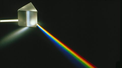
White light can be split up to form a Refers to the visible spectrum, the range of the electromagnetic spectrum visible to the human eye. It can be seen when white light is split by a prism, or by raindrops to form a rainbow. using a A block of glass or other transparent material that disperses light to form a spectrum..
This is a block of glass with a triangular cross section.
Light waves are refracted as they enter the glass because they are slowed down.
The spectrum is produced because different colours of light travel at different speeds in glass.
Red light is slowed down least by glass and is refracted least.
Violet light is slowed down most by glass and is refracted most.
As a result, the coloured light spreads out to form a spectrum of white light.
This is called dispersion.
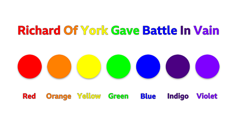
An easy way to remember the order of the colours from longest wavelength to the shortest is to use the sentence:
Richard Of York Gave Battle In Vain.
For remembering the order of the colours by the highest frequency to the lowest, it is the same colours but in the opposite order:
Violet, Indigo, Blue, Green, Yellow, Orange and Red.
Extended syllabus content: Monochromatic light
If you are studying the Extended syllabus, you will also need to know about monochromatic light. Click 'show more' for this content:
White light is made of all the colours of light, each of which has a different frequency. Monochromatic light is made from waves of only one frequency of light. It cannot be dispersed.
Quiz
Test your knowledge with this quiz on reflection and refraction.
Teaching resources
Are you a physics teacher looking for more resources? Share these short clips related to the topic of light with your students:
More on Waves
Find out more by working through a topic
- count3 of 5
- count4 of 5

- count5 of 5
- count1 of 5