Designers use many techniques to create products and solve problems. Sketches are used at the early stages with annotation to illustrate the designer’s thoughts. Development of the final design will involve creating working drawings and parts lists to enable a third party to manufacture the design.
Modelling can be used throughout the design stages to help illustrate, evaluate and refine design ideas.
ANIMATION SEQUENCE - Learning outcomes
JOE:
Hello and welcome to another episode of Tech Bitez. I have been wanting to update the Tech Bitez workshop for a while now. So I’ve been in contact with a local artist to see about getting a lovely big set piece designed. So after a lot of emails, some technical drawings, and even a computer-generated model, we finally have a finished piece. Really looking forward to showing you this. I did all the measurements and drawings myself. I got the box right here. Let's get this unboxing video underway.
SANDY:
I'm excited to see this. I wouldn't mind seeing those technical drawings too.
JOE:
Yeah yeah, I'll show you them too, just let me get this out of the box first. Where is it? Did they just send me an empty box? Wait. Is this it? What? It's supposed to be, a lot bigger. I don't understand. I was so detailed with my sketches.
SANDY:
Okay Joe, I think we would need to take a look at those technical drawings of yours.
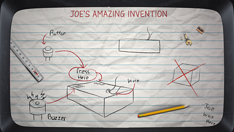
ANIMATION SEQUENCE - Animated plan of Joe's isometric drawings and measurements
SANDY:
These look great Joe. I have to say, I'm impressed. You have included everything I would expect to see in a working drawing. Let's have a look at your isometric drawing. These are very useful for showing measurements as well as how certain components will fit together. The main things to remember when producing an isometric drawing is that all horizontal lines are to be drawn at a 30 degree angle. Vertical edges are drawn as vertical lines. And lastly, parallel edges appear as parallel lines.
They're used to show a 2D graphical representation of a 3D object. You're explored a diagram looks great. That would be very useful to the manufacturer. Exploded diagrams show how a product is to be assembled and how the separate parts fit together. The dotted lines show where each part is to slide into place. They can also show components that would usually be hidden.
Lastly, we have your orthographic projections. They also look great, but I can see now where you've gone wrong. The diagrams look good. You have successfully shown the product from all angles with each correctly lined up. You have also used the correct symbol to indicate the third angle view. The first angle symbol should look like this. And the third angle symbol Like this. It's with your measurements that you have slipped up. The pieces has been produced to the exact size you requested. I assume you meant 1500 millimetres, not 150 millimetres. If you had only got out a measuring tape to visualise the size, this could have been easily avoided.
SANDY:
The artist has made it exactly to specification. How do you mess that up every time?
Freehand sketches
Freehand sketching is the quickest way of getting your initial designs on paper before an idea is forgotten. Freehand sketches are often done without a ruler or template and instead are produced quickly and freely.
Labelling of a diagram. can be added at any point to show key parts, sizes, materials, Parts that when put together makes a product. and How an item is put together.. The use of shading, colour and different viewpoints can be an easy way of communicating initial ideas.
Isometric drawings
Isometric drawings are commonly used in technical drawing to show an item in three dimensions (3D) on a page. Isometric drawings, sometimes called isometric projections, are a good way of showing measurements and how components fit together.
There are three main rules to isometric drawing:
- horizontal edges are drawn at 30 degrees
- vertical edges are drawn as vertical lines
- parallel edges appear as parallel lines
Isometric drawings are used to show a graphical representation of a 3D object. They are used by architects and engineers to communicate their ideas to the client and manufacturer, showing the product or design to .
Two cubes drawn in isometric:
Modelling of design ideas
Modelling can be time-consuming and expensive, but a physical model allows a person to see and handle a product unlike viewing it on a screen through The process of creating a 2D or 3D design using computer software..
The manufacture of a part or product from a computer aided design (CAD) using computer-controlled machinery, such as a 3D printer. models made on a 3D printer using a CAD drawing are very accurate but also expensive, time-consuming and limited to 3D-printable materials.
Product designers can use easy-to-form and easily accessible materials, eg A very lightweight hardwood used for modelling. and cardboard, to create cheap models quickly and cheaply.
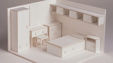
Models can be used to help:
- test the solutions functionality and whether the design is fit for purpose before selection for development and manufacture
- others, including a client, to see how the solution will look and provide feedback
- plan for manufacture, including suitable sizes and materials
Modelling and prototyping to help with the design process
NARRATOR:
Impressive, you've completed it.
UPBEAT QUIET JAZZ MUSIC
Oh, it's got a bit of a wobble on.
But you built it exactly as planned.
Maybe there was a flaw in your original design?
Hm, you might have been better off testing out your design before trying to sit on it.
This is Gareth.
Gareth is a product designer and knows that it's a good idea to test out your design using modelling and prototyping.
GARETH:
So designers can present their ideas to users, clients, and manufacturers as models and prototypes.
Models and prototypes allow clients and potential customers to visualise the product more easily than by simply looking at drawings.
A model is a scaled-down representation of a design so we can test our ideas and identify any possible issues before committing to decisions.
Models are quick and inexpensive and can be made from paper, card, foam-core board, or MDF.
Prototypes are full-size working products which allow you to test the design before manufacture.
Rapid prototyping is using techniques like 3D printing to quickly make a scale model of the entire product or a part of the product.
It allows you to test your ideas at relatively low cost ahead of production.
They also enable the designer to feel the design and check the parts fit together.
This is a bottle that we designed that allows you to track the amount of water that you're drinking.
When we're designing this bottle, we produced a model using an existing plastic drinks bottle and an elastic band.
We had the bottlehead prototyped to test our counter concept and used the elastic band to simulate the spring mechanism.
This model proved the principle of our concept which gave us the confidence to move forward with the project.
Here is an example of a 3D printed prototype that we made to test in more detail.
This included a spring-loaded mechanism which helps simulate the product performance.
It was essential to do this before we invested significant cost into the product.
Modelling and prototyping should mean your final product fulfils its requirements.
NARRATOR:
Okay, so a bit of planning, a model, and some testing next time, don't you think?
PLAYFUL MUSIC
Test yourself
More on Design and communication
Find out more by working through a topic
- count1 of 4
- count2 of 4