Key points
- Pneumatics uses compressed air to power machines and equipment, providing a clean, efficient, and safe method for various applications.
- Pneumatic systems are used in automated machinery, robotics, packaging, and construction to control movement and power tools.
- Component choice in pneumatic systems depends on force and speed requirements, operating environment, cost, and safety considerations.
- Double-acting cylinders use compressed air to move a piston rod in both directions, commonly used in manufacturing, packaging, and robotics.
- A 5/2 valve can control a double-acting cylinder more efficiently than two 3/2 valves, offering a compact design with five ports and two positions.
- Speed control in pneumatic systems is achieved using unidirectional and bidirectional flow control valves, which regulate airflow to control cylinder speed.
Overview of pneumatic control systems
A summary of pneumatic control systems
Pneumatic systems use the energy stored in compressed air to produce the required effect. By controlling the flow and release of air through pneumatic components we can achieve complex sequences of motion. Pneumatic components can be arranged in circuits, similarly to electronic circuits. Each component has its own specific symbol. These can be used to design and communicate the layout of a pneumatic circuit.
Here are some examples of the most common pneumatic components.
Single acting cylinder (SAC) and a Double acting cylinder (DAC)
A single acting cylinder will only extend through pressure from the pump. The built-in spring then returns it to its original position. A double acting cylinder will use hydraulic power to both extend and retract.This is the symbol for the exhaust, this is where the pressurised air can escape.
This symbol represents the pressure source.
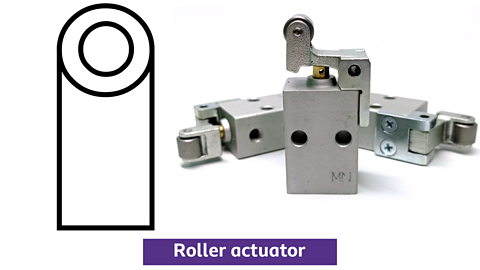
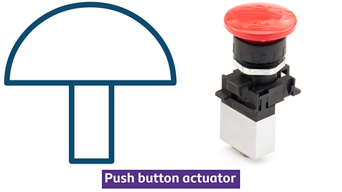
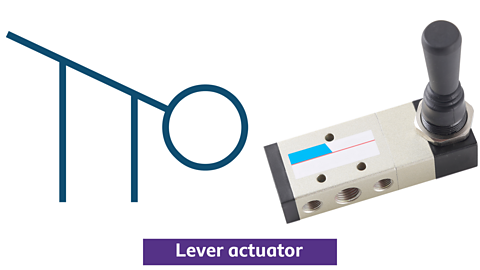
These symbols represent some of the most common actuators or inputs. Similar to an electronic circuit this is how you can interact with the pneumatic circuit.
This is a push button; plunger; roller trip; and a lever
This symbol represents a 3/2 valve. It’s called a 3/2 valve because it has 3 ports on each of its 2 positions. These can be used to control the pneumatic flow.
Any of the actuators can be attached to the 3/2 valve to act as the input.
A unidirectional flow regulator, which is this symbol, can be used to incorporate speed control into a system.
Another type of control that can be added is a shuttle valve, which looks like this. A shuttle valve will ensure that the compressed air is only able to flow from one direction. This would be important if there are different inputs.
This example shows a simple system that includes a shuttle valve. As you can see there are 2 inputs that could activate the single acting cylinder. By adding the shuttle valve we can ensure that only one source can control the system at any one time. This is known as an OR circuit. One one or the other of the inputs can activate the system.
This circuit is an example of an AND circuit. As you can see we again have 2 inputs in this circuit. However, in this case input 1 and input 2 must be engaged to activate the circuit. That is where it gets the name an AND circuit from.
What are types of pneumatic products?
Pneumatics is a branch of engineering that uses compressed air to do work. It is a clean, efficient, and safe way to power machines and equipment. Pneumatic systems are used in a wide variety of applications, including industrial automation, packaging, and transportation. They are also used in many everyday products, such as power tools, air brakes, and door openers.

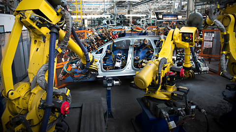
Pneumatic control systems are used in various applications, including:
- automated machinery: pneumatic systems are used to control the movement of parts in automated machinery.
- robotics: pneumatic systems are used to power the movement of robots.
- packaging: pneumatic systems are used to operate packaging machinery.
- construction: pneumatic systems are used to power tools such as jackhammers and nail guns.
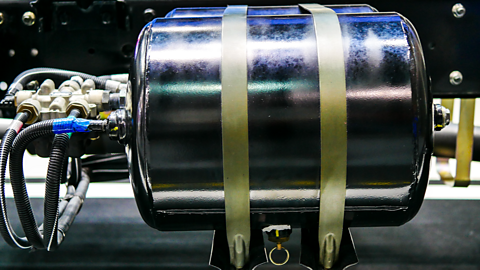
Key fact
A compressor is used to store compressed air
What components should be chosen?
- Force and speed requirements: the size and type of cylinder will depend on the force and speed needed for the application.
- Operating environment: the components must be suitable for the environment in which they will be used, considering factors such as temperature, humidity, and dust.
- Cost: the budget for the system will influence the choice of components.
- Safety: the components must be chosen to ensure the safety of operators and equipment.
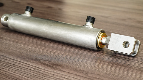
What are double-acting cylinders (DAC)
Double-acting cylinders are a type of pneumatic actuator that uses compressed air to move a piston rod in both directions. Like the way a single-acting cylinder moves a piston rod, but double-acting cylinders have two ports for extending and retracting the piston rod, while single-acting cylinders have only one port and require a spring to return the piston rod. Double-acting cylinders are commonly used in various applications, such as manufacturing, packaging, and robotics.
How to retract a double-acting cylinder
The double-acting cylinder can be controlled using two 3/2 valves.
In the circuit diagram, when either 3/2 valve is activated by pressing the push button, this will allow the compressed air to flow to the DAC. If Valve X is pressed, it will make the DAC outstroke. If Valve Y is pressed, it will make the DAC instroke.
Another method of controlling a double-acting cylinder is with a 5/2 valve.
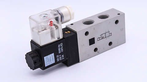
What is a 5/2 valve?
While two 3/2 valves can control the extension and retraction of a double-acting cylinder, a single 5/2 valve can achieve the same result with a more compact and efficient design. This type of valve offers five ports and two positions, allowing it to control both the flow of compressed air to the cylinder's extend and retract ports and the exhaust of air from the cylinder.
Compressed air is connected to port 1 of the 5/2 valve. In the diagrams, compressed air flowing is represented in red and exhaust air is represented in blue.
To make the DAC outstroke, the lever switch is flicked, air flows from port 1 to port 4, allowing air to go into the DAC.
Any air that was on the instroke side of the DAC, is pushed back through port 2 and out through exhaust port 3.
To make the DAC instroke, the lever switch is flicked again, connecting port 1 to port 2, allowing air to go into the DAC.
Any air that was on the outstroke side of the DAC, is pushed back through port 4 and out through exhaust port 5.
How to actuate a valve
1 of 5
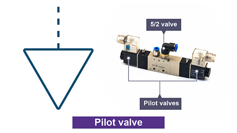
5/2 valves can be actuated in various ways, including:
- Lever: a lever is a simple mechanical device that can be used to manually actuate a valve.
- Push button: a push button is a momentary switch that can be used to actuate a valve with a simple press.
- Roller trip: a roller trip is a mechanical switch that is actuated by a roller passing over it.
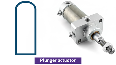
- Plunger: a plunger is a rod that can be pushed or pulled to actuate a valve.
- Pilot: a pilot is a small valve that can be used to actuate a larger valve.
How to control the speed of air in a circuit
Unidirectional flow control valve
Unidirectional flow regulators, also known as one-way flow control valves (FCV), control the speed of cylinders in pneumatic circuits by restricting airflow in one direction.
- Unidirectional flow control valves contain an adjustable screw to vary the airflow restriction, limiting the cylinders' outstroke or instroke speed.
- To incorporate speed control, a unidirectional flow regulator is installed between the 3/2 or a 5/2 valve and the SAC or DAC. By adjusting the needle valve, precise control over the cylinder’s speed can be achieved, optimizing pneumatic operations for various tasks.
A unidirectional flow control valve placed between a SAC and a 3/2 valve with push button actuator. The compressed air is restricted on the outstroke of the SAC.
What are bidirectional flow control valves?
- Bidirectional flow control valves, also known as two-way flow control valves, regulate the volume of compressed air in both directions, often to control actuator speed.
- They have an adjustable screw to control airflow and are used where precise speed control is needed.
- These valves can be used to control the speed of a pneumatic cylinder in both the outstroke and instroke.
Can you describe the pneumatic circuit?
- The pneumatic circuit shows a 5/2 valve with a push button and spring return actuator.
- The 5/2 valve is being used to control the double-acting cylinder.
- The bidirectional flow control valve will slow both the outstroke and instroke motions, as it restricts the flow of compressed air when both entering and exiting the DAC.
How time delays work
A reservoir, a small storage tank for compressed air, is crucial for creating time delays in pneumatic circuits. It works in conjunction with a flow control valve, which restricts the amount of air passing through it. When the compressed air enters the reservoir through the flow control valve, it fills gradually due to the restricted flow. This delayed filling creates a time delay before the connected actuator receives enough pressure to activate.
The duration of this delay can be adjusted by changing the setting on the flow control valve. A more restricted flow leads to a longer delay, as the reservoir takes longer to fill.
What happens when the START push button is pressed?
- Compressed air flows to the T-connector and turns left into the pilot air line (dotted line).
- The flow control valve restricts the compressed air, slowing it down.
- The compressed air then enters the reservoir, acting as a time delay, it slowly fills up due to the flow control valve.
- When the reservoir is filled, the compressed air activates the pilot operated 3/2 valve, which makes the single-acting cylinder outstroke.
What is automatic reciprocation?
Automatic and semi-automatic reciprocation in pneumatics refers to systems that create repetitive back-and-forth movements without continuous manual input. These systems are widely used in industrial automation, robotics, packaging, and construction to improve efficiency.
Typically, roller tripped or plunger activated 3/2 valves are placed on the outstroke or instroke of a cylinder. When activated the 3/2 valve then triggers another part of the pneumatic circuit, without human interaction, creating an automatic or semi-automatic pneumatic system.
How does it work:
- When Valve A (a roller tripped 3/2 valve) is activated, it allows pilot air to enter the 5/2 valve at Y, allowing air to flow from port 1 to port 4.
- Air travels into the double-acting cylinder, making it outstroke.
- When the DAC outstrokes, it is no longer activating Valve A so it then hits Valve B (also a roller tripped 3/2 valve).
- Valve B allows pilot air to enter the 5/2 valve at X, allowing air to flow from port 1 and port 2.
- Air travels into the DAC, making it instroke.
- When the DAC instrokes, it is no longer activating Valve B so it then hits Valve A.
- This repeats the steps above, creating an automatic reciprocating pneumatic circuit.
What forces are in a pneumatic cylinder?
What would happen to the double-acting cylinder if both Valve X and Valve Y were pressed at the same time?
- The DAC outstrokes only halfway
- The DAC outstrokes
- The DAC instrokes
2. The DAC outstrokes
So why does the double-acting cylinder behave in this way?
ANSWER - It is due to the force of the air pressure and the surface areas inside the double-acting cylinder.
The force exerted by a piston in a pneumatic cylinder is directly proportional to the air pressure and the piston's surface area. This relationship is expressed by the formula:
Force (N) = Pressure (N/mm²) × Area (mm²)
Where:
- Force is measured in Newtons (N)
- Pressure is measured in N/mm² (0.1 N/mm² = 1 bar)
- Area is measured in mm²
To calculate the force exerted by a pneumatic cylinder, you need to know the air pressure and the piston's cross-sectional area (CSA).
The CSA of a cylinder is the area of the circle formed by its piston. It can be calculated using the formula:
CSA (mm²) = πr²
Where:
- π (pi) is a mathematical constant approximately equal to 3.14
- r is the radius of the piston (half of its diameter)
Calculate the force exerted to make the double-acting cylinder outstroke:
Force (N) = Pressure (N/mm²) x Area (mm²)
Force = 0.4 x πr²
Force = 0.4 x (3.14 x 5²)
Force = 0.4 x (3.14 x 25)
Force = 0.4 x 78.5
Force = 31.4 N
Calculate the force exerted to make the double-acting cylinder instroke:
The piston rod has a diameter of 3mm, so it will reduce the CSA on the side of the cylinder that instrokes.
Piston rod CSA=πr²
= 3.14 x 1.5²
= 3.14 x 2.25
= 7.07mm²
Therefore, the overall CSA of the side of the cylinder with the piston rod = 78.5mm² – 7.07mm² = 71.43mm²
The force can now be found:
Force (N) = Pressure (N/mm²) x Area (mm²)
Force = 0.4 x 71.43
Force = 28.57 N
The outstroke force exerted by the piston = 31.4 N
The instroke force exerted by the piston = 28.57 N
Resulting in the cylinder outstroking if air is supplied to both sides of the double-acting cylinder.
Test yourself
More on Mechanical and pneumatic control systems
Find out more by working through a topic
- count7 of 7
- count2 of 7
- count3 of 7