Key points about conversion of motion
- A cam converts rotary motion into reciprocating motion in the follower
- Eccentric cams create a gentle up-and-down motion
- Pear cams create a quick rise and slow fall motion
- Heart cams create uniform motion with constant speed
- Snail cams create a slow rise followed by a sudden drop
- Crank and slider, rack and pinion, screw threads, and ratchet and pawl mechanisms convert different types of motion
Conversion of rotary motion to reciprocating motion using cams
A cam is a rotating piece that converts rotary motion into reciprocating motion in the follower. Think of it like a spinning shape pushing something up and down.
Eccentric/off centre cam: this is the simplest cam - imagine a wheel mounted off-centre. As it rotates, it creates a gentle up-and-down motion, like what you might find in a simple mechanical toy.
Pear/egg cam: shaped like a pear, this creates a quick rise and slow fall motion. You might find this in machinery where you need something to lift quickly but lower gently.
Heart cam: this special shape creates a uniform motion - meaning the follower moves at a constant speed up and down. This is useful in machinery where smooth, consistent movement is important, like in sewing machines.
Snail/drop cam: creates a slow rise followed by a sudden drop. Imagine a door closer mechanism - it closes the door slowly but lets it open quickly.
Types of follower
- Flat
Flat followers have a flat bottom that sits on the cam. These cope well under load but aren’t very accurate and have a lot of Friction is a force that opposes motion. It can make things harder to move..
- Knife
Knife followers have a narrow point that sits on the cam. These are very accurate and low friction but are quick to wear away the pointed edge.
- Roller
Roller followers have a roller such as a ball bearing attached to the bottom of the following. These are accurate, low on friction and can withstand load, but are more costly to produce.
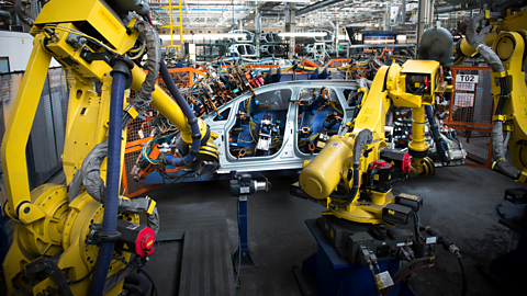
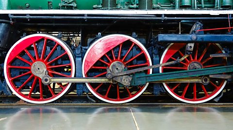
What is a crank and slider?
A crank and slider converts rotary motion to reciprocating motion (or vice versa). Picture a train's wheels and connecting rods - as the wheel (crank) turns, it makes the piston (slider) move back and forth. This is also how a petrol engine converts the up-and-down motion of pistons into the rotating motion of the The rotating shaft to which a crank is joined.
What is a rack and pinion mechanism
An example of this is in a pillar drill, where the table bed is moved up and down.
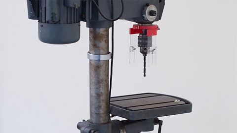
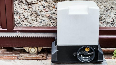
A Rack and Pinion converts rotary motion to linear motion using a gear (pinion) that meshes with a toothed bar (rack). When the gear turns, the rack moves in a straight line. This is used in car steering systems - turning the steering wheel (rotary) makes the wheels turn left or right (linear). Can also be used to open and close an electric gate, with the motor (rotary) makes the gate move left or right (linear).
Conversion of motion using screw threads
Screw threads convert rotary motion to linear motion by using spiral grooves. When you turn a screw (rotary), it moves forward or backward (linear). Examples include machine vice in workshops, jar lids, and bottle caps. The thread angle determines how far the screw advances with each rotation.
What is a ratchet and pawl?
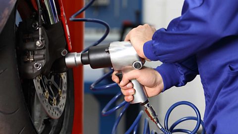
A ratchet and pawl mechanism allows rotation in one direction while preventing reverse motion. Think of a bicycle's free wheel - you can pedal forward, but the wheel won't spin backwards. The ratchet is a wheel with angled teeth, and the pawl is a finger that fits between them. It's also used in socket wrenches and hand winches.
Test yourself
More on Mechanical and pneumatic control systems
Find out more by working through a topic
- count5 of 7
- count6 of 7
- count7 of 7