Key points
- Freehand sketching is the quickest way to capture initial design ideas on paper before they are forgotten, often done without rulers or templates.
- Annotation can be added to sketches to show key parts, sizes, materials, components, and construction, using shading, colour, and different viewpoints for clarity.
- The Black Box method generates ideas for electronic systems by focusing on inputs and outputs without needing to understand the complex internal details, encouraging creative solutions.
- Circuit diagrams use standard symbols to represent electronic components, making it easy to understand connections and essential for explaining how an electronic solution might work.
- Circuit simulation software can test and refine designs before further development, ensuring accuracy and functionality.
This section is relevant for students embarking on their design and manufacturing project and who are pursuing either Option A: Electronic and Microelectronic Control Systems; or Option B: Mechanical and Pneumatic Control Systems. Typically referred to as the Systems pathway.
Making use of freehand sketches
Freehand sketching is the quickest way of getting your initial designs on paper before an idea is forgotten. Freehand sketches are often done without a ruler or template and instead are produced quickly and freely.
Annotation of ideas
Annotation can be added at any point to show key parts, sizes, materials, components and construction. The use of shading, colour and different viewpoints can be an easy way of communicating initial ideas.
How to use Black Box ideas
The Black Box method is a way to generate ideas for how an electronic system might work without needing to understand the complex details inside.
Imagine the system as a black box – you know what goes in (input) and what comes out (output), but not what happens inside.
For example, with a kettle, the input is electricity and water, and the output is boiling water. You can then brainstorm different ways the system could achieve this output, like using a heating element to heat the water.
This encourages creative thinking about different solutions without getting bogged down in technical details.
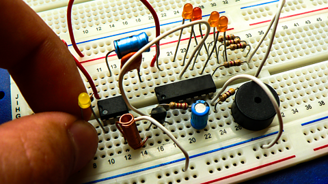
How to design circuit diagrams

Circuit diagrams are essential for explaining how an electronic solution might work. They use standard symbols to represent components like resistors, capacitors, and transistors, making it easy to understand the connections between them.
Using the correct symbols is important for clear communication and to avoid confusion. Circuit simulation software can also be used to test and refine designs before developing them further.
Test yourself
Further study
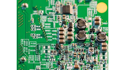
What are Printed Circuit Boards (PCBs)? revision-guide
Find out how to design a PCB from a circuit diagram
How to develop and generate your ideas. revision-guide
Brush up on freehand sketching

More on Systems pathway
Find out more by working through a topic
- count2 of 3