What are the key learning points about Ohm's law?
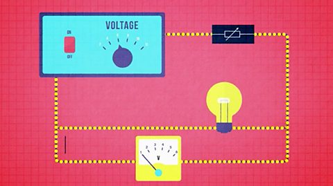
Ohm’s Law can be demonstrated for a metal wire; a can be used to measure the The potential difference across a cell, electrical supply or electrical component. It is measured in volts (V). across the wire and an A device used to measure electric current. to measure the current passing through the wire.
The temperature of the wire is kept constant using a switch and small currents.
A voltage–current characteristic graph (V-I graph) can be plotted, with voltage on the y-axis and current on the x-axis;
- the V-I graph is a straight line that passes through the origin, this shows that the current and voltage are When one variable is zero so is the other. As one variable increases the other does at the same rate. When 𝒚 is plotted against 𝒙 this produces a straight-line graph through the origin. for a metal wire at constant temperature, and that this is known as Ohm’s law.
The equation voltage = current × resistance where voltage is measured in volts, current in amperes and in ohms.
The voltage–current characteristic graph (V-I graph) for a A thin, high resistance wire that gets hot and glows when a current flows through it causing it to emit heat and light. Filaments are used in some types of bulb and electrical heaters. lamp is a curve with increasing In a graph, the gradient is the steepness of the line. The greater the gradient, the greater the rate of change. which shows that the resistance of a filament lamp increases as the current through the filament increases.
An electrical current flowing through a metal wire generates heat in terms of Negatively charged sub-atomic particles that can move through the structure of a substance, usually a metal or graphite. A material with many free electrons is a good conductor.All elements are made of atoms. An atom consists of a nucleus containing protons and neutrons, surrounded by electrons. collisions.
The Data that is described in numbers. relationships energy = power × time and power = current × voltage can be used to calculate energy in joules (J), power in watts (W), current in amps (A), voltage in volts (V) and the time in seconds (s).
What is resistance in an electric circuit?
All conductors show some opposition to electric current.
This opposition to current is called resistance.
A good conductor has low resistance.
A poor conductor, or insulator, has high resistance.
The two main ways of increasing the current in an electrical circuit are by increasing the voltage or by decreasing the resistance.
Changing the voltage
If you increase the voltage across a component, for example a lamp, there will be more current in the component.
Too high a voltage and the lamp will break.
Changing the resistance
If you increase the number of lamps in a series circuit, there will be less current.
The lamps resist the current, so if you put more lamps into the circuit, there is more resistance.
You could increase or decrease the resistance in a circuit by using a variable resistor (also known as a rheostat).
Prescribed practical P7: Ohm's law
How to safely plan and carry out an investigation into Ohm's law
What is the purpose of prescribed practical P7?
To use a voltmeter to measure the voltage across a metal wire and an ammeter to measure the current passing through the wire, and:
demonstrate understanding that the temperature of the wire is kept constant using a switch and small currents.
demonstrate understanding of the need to obtain sufficient values of voltage and current so that a voltage–current characteristic graph (V-I graph) can be plotted, with voltage on the y-axis and current on the x-axis.
recall that the V-I graph is a straight line that passes through the origin.
recall that this shows that the current and voltage are proportional for a metal wire at constant temperature, and that this is known as Ohm’s law.
What are the main variables?
The main variables in a science experiment are the independent variable, the dependent variable and the control variables.
The independent variable is what we change or control in the experiment.
The dependent variable is what we are testing and will be measured in the experiment.
The control variables are what we keep the same during the experiment to make sure it’s a fair test.
In this experiment:
The independent variable is the electric current I.
The dependent variable is the voltage V.
The control variables are the material, length, cross section area and temperature of the wire.
These are kept the same by not changing the wire during the experiment, by keeping the current small and opening the switching between readings.
Remember - these variables are controlled (or kept the same) because to make it a fair test, only 1 variable can be changed, which in this case is the current.
What is the prediction for this experiment?
As the current increases, the voltage will also increase.
What is the justification for the prediction?
Greater current will mean that more charge flows.
This means that more energy can be converted from electrical energy to other forms of energy and so voltage increases.
How to manage this experiment safely
| Hazard | Electric shock | Control measures |
|---|---|---|
| Water | Electric shock | Do not set up the experiment near taps, sinks etc. |
| Wire gets hot | Minor burns | Do not handle the wire. Switch off between readings. |
What apparatus is used in prescribed practical P7?
1m length of constantan wire, a metre rule, a low voltage power pack, a variable resistor, a voltmeter, an ammeter, connecting leads, a switch, 2 crocodile clips, Sellotape.
Circuit diagram
How to carry out prescribed practical P7
Set up the circuit, as shown above.
Adjust the variable resistor until the current on the ammeter is 0.1 A. Record the current in a suitable table.
Read the corresponding value of voltage across the wire on the voltmeter and record in the table.
Turn the switch off between all readings to prevent the temperature of the wire rising.
Turn on again. Ensure that the current is still 0.1 A and repeat the voltage reading. Calculate the average voltage.
Repeat the procedure for six more values of current up to 0.7 A.
How to avoid errors when carrying out prescribed practical P7
The temperature of the wire must be kept constant.
Whenever a current flows through a conductor there is a heating effect.
Electrical energy is converted to heat energy.
To ensure the temperature of the wire does not increase, switch off between readings and keep the current as small as possible.
Results
| Current I / A | Voltage V / V | Voltage V / V | Voltage V / V |
|---|---|---|---|
| Reading 1 | Reading 2 | Average voltage | |
| 0.00 | |||
| 0.10 | |||
| 0.20 | |||
| 0.30 | |||
| 0.40 | |||
| 0.50 | |||
| 0.60 | |||
| 0.70 |
Graph
What conclusion can be drawn from an investigation into Ohm's law?
We can see from the graph that as the current increases the voltage also increases.
This agrees with our prediction.
In fact, since the line of best fit is a straight line through the origin, we can be even more precise.
We can say that the voltage across the wire is When one variable is zero so is the other. As one variable increases the other does at the same rate. When 𝒚 is plotted against 𝒙 this produces a straight-line graph through the origin. to the current flowing through it.
As the voltage increases the current increases in direct proportion.
This is known as Ohm’s Law.
Key facts
Ohm’s law states that the voltage across a conductor is directly proportional to the current flowing through it, provided all physical conditions, such as temperature, remain constant.
A conductor that obeys Ohm’s law is called an ohmic conductor.
Copper or constantan wire are examples of ohmic conductors.
What is the current, voltage and resistance equation?
Current, voltage and resistance are related by the equation:
voltage V = current I x resistance R
V= IR
V = voltage in V
I = current in A
R = resistance in \(\Omega\)
| V = IR | V = I x R |
| I = \(\frac{\text{V}}{\text{R}}\) | I = V ÷ R |
| R = \(\frac{\text{V}}{\text{I}}\) | R = V ÷ I |
Question
A torch lamp takes a current of 0.3 A from a 3 V battery.
Calculate its resistance.
Answer
V = 3 V
I = 0.3 A
R = \(\frac{\text{V}}{\text{I}}\)
R = \(\frac{\text{3 V}}{\text{0.3 A}}\)
R = 10 \(\Omega\)
The resistance of the lamp is 10 \(\Omega\)
Question
Calculate the reading on the ammeter in the circuit shown below.
Answer
V = 12.0 V
R = 2.7 x 10³ \(\Omega\)
I = \(\frac{\text{V}}{\text{R}}\)
I = \(\frac{\text{12.0 V}}{\text{2.7 x 10}^3\Omega}\)
I = 0.0044 A = 4.4 x 10⁻³ A = 4.4 mA
The reading on the ammeter is 4.4 mA.
Question
3 A flows through a 240 V lamp. What is the resistance of the lamp?
Answer
R = \(\frac{\text{V}}{\text{I}}\)
V = 240 V
I = 3 A
I = \(\frac{\text{240 V}}{\text{3 A}}\)
R = 80 \(\Omega\)
The resistance of the lamp is 80 \(\Omega\)
How does resistance work in an electric circuit?
Electric current is due to the flow of free Negatively charged sub-atomic particles that can move through the structure of a substance, usually a metal or graphite. A material with many free electrons is a good conductor. through a conductor.
Electrons can move more easily through some conductors than others, whenever a voltage is applied.
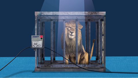
The opposition of a conductor to the flow of current is called its resistance.
Resistance is measured in ohms (\(\Omega\)).
The electrical symbol for a resistor is:
A good conductor has a low resistance and a poor conductor, called an insulator, has a high resistance.
Electric wires are made of metal, which have electrical resistance.
The atoms in a solid metal are arranged in a regular A regular grid-like arrangement of atoms in a material. structure.
The outer electrons from each atom are free to move through the structure.
When these flow in the same direction a current flows.
However, they may collide with Electrically charged particle, formed when an atom gains or loses electrons. of the metal or meet defects in the lattice.
Hence, there is resistance to the current flow, which in turn, reduces the size of the current.
Key facts
Resistance in a conductor is due to collisions between the flowing free electrons and the ions in the lattice structure.
More electron-ion collisions mean greater resistance.
When collisions between electrons and ions occur, electrical energy is converted to heat.
Investigate the voltage-current (V-I) relationship of a filament lamp
Higher tier only
What is the purpose of this experiment?
Describe and carry out an experiment to obtain the voltage–current characteristic graph (V-I graph) for a filament lamp with voltage on the y-axis and current on the x-axis.
Show that the resistance of a filament lamp increases as the current through the filament increases by taking the ratio of the voltage to the current at different values of the current.
The voltage across and the current through a component (eg a filament lamp) can be measured and the results plotted on a graph to show the V-I characteristic of the component.
In this practical activity, it is important to measure and observe the voltage and current accurately.
Method
Connect the circuit as shown in the diagram above.
Adjust the variable resistor until the voltmeter reads 1 V.
Record the readings on the ammeter and on the voltmeter in a suitable table.
Adjust the variable resistor to increase the voltmeter reading to 2 V.
Record the new readings on the ammeter and the voltmeter in the table.
Repeat steps 4 and 5, increasing the voltage in steps 1 V, until the voltmeter reads 12 V.
Results
| Voltage V / V | Current I / A | Resistance R / Ω (\(R = \frac{V}{I}\)) |
|---|---|---|
| 0 | 0 | |
| 1.00 | 0.40 | |
| 2.00 | 0.60 | |
| 3.00 | 0.78 | |
| 4.00 | 1.00 | |
| 5.00 | 1.15 | |
| 6.00 | 1.25 | |
| 7.00 | 1.36 | |
| 8.00 | 1.41 | |
| 9.00 | 1.46 | |
| 10.00 | 1.50 | |
| 11.00 | 1.53 | |
| 12.00 | 1.55 |
How to analyse the results of this experiment
For each pair of results calculate the resistance, R using \(R = \frac{V}{I}\).
Record your results in the third column of the table.
Plot a graph of voltage, V on the y-axis v current, I, on the x-axis.
Evaluation
For a filament lamp, voltage and current are not directly proportional as the graph is not a straight line through the origin.
Doubling the voltage does not double the current.
It is clear from the resistance column in the results table that, as current increases the resistance of the lamp increases.
As the current through the lamp increases, the filament gets hotter and has a higher resistance.
Conclusion
The resistance of a filament lamp increases as the current through the filament increases and hence as the temperature increases.
Risk assessment
| Hazard | Risk | Control measures |
|---|---|---|
| Hot lamps can burn. | Burns to the skin from hot lamps. | Do not touch the lamp whilst the circuit is connected; allow time for the lamp to cool. |
| Water | Electric shock. | Do not set up the experiment near taps, sinks etc. |
What is the relationship between resistance and temperature?
The Negatively charged sub-atomic particles that can move through the structure of a substance, usually a metal or graphite. A material with many free electrons is a good conductor.collide with Electrically charged particle, formed when an atom gains or loses electrons. of the metal as they pass through the conductor.
As a result, the free electrons lose electrical energy and the metal ions gain energy.
This causes them to vibrate faster and with bigger The amplitude of a wave is its maximum displacement from its undisturbed position. – which means a higher temperature.
The heating effect of an electric current is useful in devices such as electric heaters, toasters, grills, hair dryers and straighteners.
The heating effect of an electric current is not useful in devices such as televisions, filament lamps, electric drills and battery chargers.
Key fact
The resistance of a metal conductor is due to collisions between the free electrons of the electric current and the metal Electrically charged particle, formed when an atom gains or loses electrons. of the wire.
If the temperature of a metal conductor increases, the ions of the metal vibrate more vigorously.
This increases the number of collisions between the Negatively charged sub-atomic particles that can move through the structure of a substance, usually a metal or graphite. A material with many free electrons is a good conductor. and the ions.
Hence, for a metal, resistance increases with increasing temperature.
Often the increase in temperature is caused by an increase in current.
An example is a lamp.
As current increases, the filament gets hotter and the resistance of the lamp increases.
How does heat energy transfer to the wires from electric current?
As Negatively charged sub-atomic particles that can move through the structure of a substance, usually a metal or graphite. A material with many free electrons is a good conductor. flow through wires, they collide with the Electrically charged particle, formed when an atom gains or loses electrons. in the wire which causes the ions to vibrate more.
This increased vibration of the ions increases the temperature of the wire.
Energy has been transferred from the electrical energy carried by the electrons into the internal energy of the wire.
Electric power
The electric power (or the amount of energy transferred each second) can be calculated using the equation:
power = current × voltage
P = VI
where:
| \({P} = {VI}\) | \({P} = {V}\times{I}\) |
| \({I} =\frac{\text{P}}{\text{V}}\) | \({I} = {P} \div {V}\) |
| \({V} = \frac{\text{P}}{\text{I}}\) | \({V} = {P} \div {I}\) |
Remember that one watt is equal to one joule per second (1 W = J/s).
How to calculate electrical energy
Since:
\({Power} =\frac{\text{energy~transferred}}{\text{time~taken}}\)
Then:
Energy = power x time
Hence:
Electric energy = electric power x time (t)
Where:
E = electric energy in joules, J
P = electric power in watts, W
t = time in seconds, s
| \({E} = {Pt}\) | \({E} = {P}\times{t}\) |
| \({P} =\frac{\text{E}}{\text{t}}\) | \({P} = {E} \div {t}\) |
| \({t} =\frac{\text{E}}{\text{p}}\) | \({t} = {E} \div {P}\) |
Since:
Electric energy = electric power x time (t)
And:
power = current × voltage
P = VI
Then:
Electric energy = VI x t
Electric energy = VI t
This is usually remembered in the form:
Electric energy = ItV
Where:
Electric energy is in joules, J
I = current in amperes, A
t = time in seconds, s
V = voltage in volts, V
Key point
- Electric power P = VI
- Electrical energy = P x t
Example question
What is the power of a small electric motor if a current of 2 A flows when connected to a 12 V power supply?
Answer
P = VI
I = 2 A
V = 12 V
P = 2 A x 12 V
P = 24 W
The power of the electric motor is 24 W.
Question
A light bulb is rated 60 W, 240 V. What does that mean?
Answer
When the voltage across the bulb is 240 V, the bulb has a power of 60 W.
It converts 60 J of electrical energy into light and heat energy every second.
Question
A kettle has a power of 2.2 kW and is connected to mains voltage of 240 V.
- What current flows when the kettle is operating normally?
- What is the resistance of the kettle’s heating element?
Answer
\({I} =\frac{\text{P}}{\text{V}}\)
P = 2.2 kW = 2200 W
V = 240 V
\({I} =\frac{\text{2200 W}}{\text{240 V}}\)
I = 9.17 A
\({R} =\frac{\text{V}}{\text{I}}\)
V = 240 V
I = 9.17 A
\({R} =\frac{\text{240 W}}{\text{9.17 A}}\)
R = 26.2 \(\Omega\)
The resistance of the kettle’s heating element is 26.2 \(\Omega\)
Test your knowledge
More on Unit 2: Electricity
Find out more by working through a topic
- count4 of 5
- count5 of 5

- count1 of 5

- count2 of 5