What are the key learning points about calculating resistance?
The total resistance of An electrical component that restricts the flow of electrical charge. Fixed-value resistors do not change their resistance, but with variable resistors it is possible to vary the resistance.in series is the sum of the individual resistances of the resistors.
The resistance of two equal resistors in parallel is always equal to half the resistance of one of the resistors.
When more than two resistors are connected in parallel the equation becomes:\(\frac{1}{R}=\frac{1}{R}_{1}+\frac{1}{R}_{2}+\frac{1}{R}_{3}\)
The resistance of a metallic conductor at constant temperature depends on length.
The graph of resistance versus length is a straight line that passes through the origin, this shows that for a metal wire at constant temperature the resistance and length of wire are When one variable is zero so is the other. As one variable increases the other does at the same rate. When 𝒚 is plotted against 𝒙 this produces a straight-line graph through the origin..
The resistance of a metallic conductor at constant temperature also depends on the area of cross section and the material it is made from.
What happens when resistors are connected in series?
Current
When resistors are connected in series, the current through each resistor is the same.
Key fact
The current is the same at all points in a series circuit.
Current does not get used up in a circuit.
In the circuit below: IS = I1 = I2 = I3
Voltage V (or potential difference)
When resistors are connected in series, the total of all the voltages (sometimes referred to as The potential difference (or voltage) of a supply is a measure of the energy given to the charge carriers in a circuit. The unit this is measured with is volts (V).) across each component is equal to the voltage across the power supply.
In the circuit above:
VS = V1 + V2 + V3
This is just a form of the law of conservation of energy.
The supply voltage is a measure of the energy supplied to each electron.
The voltage across each component is the electrical energy converted by each component.
Therefore, the energy supplied equals the energy converted – energy has not been created or destroyed in the circuit.
Key fact
In a series circuit, the voltage across the power supply equals the sum of the voltages across each component.
Resistance
The total resistance R of two or moreAn electrical component that restricts the flow of electrical charge. Fixed-value resistors do not change their resistance, but with variable resistors it is possible to vary the resistance. connected in series is the sum of the individual resistances of the resistors.
For the circuit above the total resistance R is given by:
R = R1 + R2 + R3
Example
Find the total resistance of the circuit above.
Answer
This is a series circuit and so total resistance is found using the equation:
R = R1 + R2 + R3 + R4
R = \({4} \Omega + {8} \Omega + {2} \Omega + {12} \Omega\)
R = \({26} \Omega\)
The total resistance of the network of resistors is \({26} \Omega\).
This means that the four individual resistors can be replaced by one resistor of \({26} \Omega\).
Adding resistors in series always increases the total resistance.
The current has to pass through each resistor in turn so adding an additional resistor adds to the resistance already encountered.
What happens when resistors are connected in parallel?
Current
When resistors are connected in parallel, the current from the power supply is equal to the sum of the currents through each branch of the circuit.
In other words, the currents in the branches of a parallel circuit add up to the supply current.
In the circuit above:
IS = I1 + I2 + I3
This relationship expresses the law of conservation of charge.
All electrons that set out from the supply must return to the supply and each electron can only pass through one parallel branch.
Current splitting along parallel branches
We know that if we add together all the currents in the parallel branches we get the total current.
If the resistances along each branch are the same then the current will split equally.
For example:
Alternatively if the resistances along each branch are not the same then the current will split unevenly with more current going to the easier (lower resistance path).
If one branch has twice the resistance then it will have half the current.
For example:
Key fact
In a parallel circuit, the current from the power supply equals the sum of the currents in each branch of the circuit.
Voltage
In a parallel circuit, the voltage across each branch of the circuit equals the supply voltage.
For the circuit above:
VS = V1 = V2 = V3
Key fact
In a parallel circuit, the voltage across each branch equals the supply voltage.
Resistance
When resistors are connected in parallel, total resistance, R, is calculated using the equation:
\(\frac{1}{R}=\frac{1}{R}_{1}\) + \(\frac{1}{R}_{2}\) + \(\frac{1}{R}_{3}\)
Worked examples: Calculate the resistance of two equal resistors
Example 1
Question
Calculate the resistance of the two resistors in parallel.
Answer
\(\frac{1}{R}=\frac{1}{R}_{1} + \frac{1}{R}_{2}\)
R1 = \({8}\Omega\)
R2 = \({8}\Omega\)
\(\frac{1}{R}=\frac{1}{8} + \frac{1}{8}\)
\(\frac{1}{R}=\frac{2}{8}\)
R = \(\frac{8}{2}\)
R = \({4}\Omega\)
The total resistance of the two resistors in parallel is \({4}\Omega\)
When two equal resistors are connected in parallel, the total resistance is always equal to half the resistance of one of the resistors.
This only works for two equal resistors connected in parallel and should only be used to check your answer.
Example 2
Question
Calculate the resistance of the two resistors in parallel.
Answer
\(\frac{1}{R}=\frac{1}{R}_{1}\) + \(\frac{1}{R}_{2}\)
R1 = \({50}\Omega\)
R2 = \({50}\Omega\)
\(\frac{1}{R}=\frac{1}{50} +\frac{1}{50}\)
\(\frac{1}{R}=\frac{2}{50}\)
R = \(\frac{50}{2}\)
R = \({25}\Omega\)
The total resistance of the two resistors in parallel is \({25}\Omega\)
Quick check: when two equal resistors are calculated in parallel, the total resistance is always equal to half the resistance of one of the resistors.
Half of \({50}\Omega\) is \({25}\Omega\) and so the answer is correct.
Worked example: Resistors in parallel (Higher tier only)
When more than two resistors are connected in parallel the equation becomes:
\(\frac{1}{R}=\frac{1}{R}_{1}\) + \(\frac{1}{R}_{2}\) + \(\frac{1}{R}_{3}\)…
Question
The following resistor network is set up.
Calculate the total resistance of the network.
Answer
\(\frac{1}{R}=\frac{1}{R}_{1}\) + \(\frac{1}{R}_{2}\) + \(\frac{1}{R}_{3}\)
R1 = \({12}\Omega\)
R2 = \({18}\Omega\)
R3 = \({6}\Omega\)
\(\frac{1}{R}=\frac{1}{12} + \frac{1}{18} + \frac{1}{6}\)
\(\frac{1}{R}=\frac{11}{36}\)
R = \(\frac{36}{11}\)
R = \({3.27} \Omega\)
This means that the three individual resistors can be replaced by one resistor of \({3.27} \Omega\).
Adding resistors in parallel decreases the total resistance.
The current has a choice of paths and only has to pass along one branch of the circuit.
It does not pass through each resistor and the total resistance of a parallel circuit is always smaller than the smallest resistor.
Worked example: Resistance of a network (Higher tier only)
Question
Calculate the total resistance of the network of resistors.
Answer
This circuit contains a \({5} \Omega\) resistor in series with two resistors, \({6} \Omega\) and \({4} \Omega\), which are in parallel.
Start by calculating the combined resistance of the two parallel resistors.
\(\frac{1}{R}=\frac{1}{R}_{1}\) + \(\frac{1}{R}_{2}\)
R1 = \({6}\Omega\)
R2 = \({4}\Omega\)
\(\frac{1}{R}=\frac{1}{6} + \frac{1}{4}\)
\(\frac{1}{R}=\frac{5}{12}\)
R = \(\frac{12}{5}\)
R = \({2.4} \Omega\)
The network has been simplified to:
Question
Now calculate the total resistance of the two resistors in series.
Answer
R = R1 + R 2
R = \({5} \Omega + {2.4} \Omega\)
R = \({7.4} \Omega\)
The total resistance of the network is \({7.4} \Omega\)
Example
Question
Calculate the total resistance of the network.
Answer
The two \({4} \Omega\) resistors are in parallel with each other.
The two \({10} \Omega\) resistors are in parallel with each other.
The two parallel networks are in series with each other.
First, calculate the total resistance of each parallel network:
| \(\frac{1}{R}=\frac{1}{R}_{1}\)+ \(\frac{1}{R}_{2}\) | \(\frac{1}{R}=\frac{1}{R}_{1}\) + \(\frac{1}{R}_{2}\) |
| R1 = \({4} \Omega\) | R1 = \({10} \Omega\) |
| R2 = \({4}\Omega\) | R2 = \({10}\Omega\) |
| \(\frac{1}{R}=\frac{1}{4} +\frac{1}{4}\) | \(\frac{1}{R}=\frac{1}{10} +\frac{1}{10}\) |
| \(\frac{1}{R}=\frac{2}{4}\) | \(\frac{1}{R}=\frac{2}{10}\) |
| R = \(\frac{4}{2}\) | R = \(\frac{10}{2}\) |
| R = \({2} \Omega\) | R = \({5} \Omega\) |
The network has been simplified to:
Question
Now calculate the total resistance of the two resistors in series.
Answer
R = R1 + R2
R = \({2} \Omega + {5} \Omega\)
R = \({7} \Omega\)
The total resistance of the network is \({7} \Omega\)
Worked example: Resistors in series and parallel (Higher tier only)
Question
- Calculate the total resistance of the circuit
- Calculate the current flowing in the \({3}\Omega\) resistor
- Calculate the voltage across the \({8}\Omega\) resistor
- Calculate the current flowing in the \({6}\Omega\) resistor
Answer
- First calculate the parallel resistance:
\(\frac{1}{R}=\frac{1}{R}_{1}\) + \(\frac{1}{R}_{2}\)
R1 = \({8}\Omega\)
R2 = \({6}\Omega\)
\(\frac{1}{R}=\frac{1}{8} +\frac{1}{6}\)
\(\frac{1}{R}=\frac{7}{24}\)
R = \(\frac{24}{7}\)
R = \({3.43}\Omega\)
This is in series with the \({3}\Omega\). The total resistance R is given by:
R = R1 + R2
R = \({3}\Omega + {3.43}\Omega\)
R = \({6.43}\Omega\)
The total resistance of the circuit is \({6.43}\Omega\).
- The circuit above has now been simplified to:
Hence, the voltage across the \({6.43}\Omega\) resistor is 12 V.
I = \(\frac{V}{R}\)
V = 12 V
R = \({6.43}\Omega\)
I = \(\frac{12 V}{{6.43}\Omega}\)
I = 1.87 A
The current is the same in all parts of a series circuit and so this is the current through the \({3}\Omega\) resistor too.
The current flowing in the \({3}\Omega\) is 1.87 A.
- The current through the \({8}\Omega\) resistor is not known so we cannot use V = IR to calculate the voltage across it directly.
However, we do know the current through the \({3}\Omega\) resistor, so we can calculate the voltage across it.
V = IR
I = 1.87 A
R = \({3}\Omega\)
V = 1.87 A x \({3}\Omega\)
V = 5.61 V
The total voltage = 12 V
Hence, the voltage across the two parallel resistors = 12 V – 5.61 V = 6.39 V.
The voltage across each parallel resistor is the same.
Hence, the voltage across the \({8}\Omega\) = 6.39 V.
The voltage across the 8Ω resistor is 6.39 V.
- The voltage across each parallel resistor is the same.
Hence, the voltage across the \({6}\Omega\) resistor = 6.39 V.
I = \(\frac{V}{R}\)
V = 6.39 V
R = \({6}\Omega\)
I = \(\frac{6.39 V}{{6}\Omega}\)
I = 1.07 A
The current through the \({6}\Omega\) is 1.07 A.
Key points
For components in series:
The current through each component is the same.
The voltage is shared between the components.
For components in parallel:
The supply current is shared between each parallel branch.
The voltage across each parallel branch is the same.
Prescribed practical P8: The resistance of a metallic conductor
A guide to carrying out a practical to investigate resistance
What is the purpose of prescribed practical P8?
To investigate experimentally how the resistance of a metallic conductor at constant temperature depends on length and obtain sufficient values to plot a graph of resistance (y-axis) and length (x-axis).
What are the main variables in this practical?
The main variables in a science experiment are the independent variable, the dependent variable and the control variables.
The independent variable is what we change or control in the experiment.
The dependent variable is what we are testing and will be measured in the experiment.
The control variables are what we keep the same during the experiment to make sure it’s a fair test.
In this experiment the:
Independent variable is the length of wire.
Dependent variable is the resistance of the wire.
Control variables are the material, the cross section area and the temperature of the wire, and these are kept the same by not changing the wire during the experiment, by keeping the current small and by opening the switching between readings.
Remember - these variables are controlled (or kept the same) because to make it a fair test, only 1 variable can be changed, which in this case is the length of wire.
What is the equation used for calculating resistance?
Resistance R = \(\frac{voltage~V}{current~I}\)
What is the prediction for this practical?
As the length of wire increases, the resistance will increase.
What is the justification for this prediction?
The greater the length of wire the greater the number of collisions between the Negatively charged sub-atomic particles that can move through the structure of a substance, usually a metal or graphite. A material with many free electrons is a good conductor. and metal Electrically charged particle, formed when an atom gains or loses electrons..
This will result in greater resistance.
| Hazard | Consequence | Control measures |
|---|---|---|
| Water | Electric shock | Do not set up the experiment near taps, sinks etc. |
| Wire gets hot | Minor burns | Do not handle the wire. Switch off between readings. |
What apparatus is needed for this practical?
1m length of constantan wire, a metre rule, a low voltage power pack, a voltmeter, an ammeter, connecting leads, a switch, 2 crocodile clips, Sellotape.
How to carry out prescribed practical P8?
- Set up the circuit, as shown above. Attach one of the crocodile clips at the 0 cm mark and the other at the 20 cm mark so that the length of wire the current flows through is 20 cm. Record this length in a suitable table
- Adjust the power pack until the current on the Ammeter is 0.4 A. Record the current in the table
- Read the corresponding value of voltage across the wire on the voltmeter and record in the table
- Switch the switch off to prevent the temperature of the wire rising
- Switch on again and repeat the reading of voltage. Record in the table. Switch off and calculate the average voltage
- Calculate the resistance of this length of wire and record in the table
- Switch on again. Ensure that the current is still 0.4 A and repeat current and voltage reading for lengths of 40 cm, 50 cm, 60 cm, 80 cm and 100 cm
- Calculate the resistance for each length, remembering to switch off between each reading
Error
The temperature of the wire must be kept constant.
Whenever a current flows through a conductor there is a heating effect.
Electrical energy is converted to heat energy.
To ensure the temperature of the wire does not increase, switch off between readings and keep the current as low as possible.
Results
| Length l / cm | Current I / A | Voltage V / V | Voltage V / V | Voltage V / V | Resistance R / Ω |
|---|---|---|---|---|---|
| Reading 1 | Reading 2 | Average voltage | |||
| 20 | |||||
| 40 | |||||
| 50 | |||||
| 60 | |||||
| 80 | |||||
| 100 |
Graph
Plot a graph of resistance, R, in Ω on the y-axis against length, l, in cm on the x-axis. Draw the line of best fit.
Conclusion
We can see from the graph that as the length of the wire, l, increases, the resistance, R, also increases.
This agrees with our prediction.
In fact, since the line of best fit is a straight line through the origin, we can be even more precise.
We can say that, for a metal wire at constant temperature, the resistance is When one variable is zero so is the other. As one variable increases the other does at the same rate. When 𝒚 is plotted against 𝒙 this produces a straight-line graph through the origin. to the length of the wire.
If you double the length of the wire you double its resistance.
Variable Resistors
Variable resistors can be used to control the current that is flowing in a circuit.
They do this by changing the length of some resistance wire in a circuit.
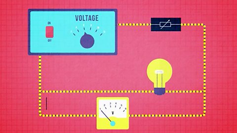
The circuit diagram below shows a variable resistor being used to control the current through a bulb.
One connecting wire is attached to the bottom left terminal and the other to the upper right terminal.
As the sliding contact on the top is moved it changes the length of resistance wire in the circuit.
Increasing the length of wire decreases the current and vice-versa.
Longer resistance wire means more electron-ion collisions hence greater resistance and reduced current.
If connections are made between the two lower terminals it will act as a fixed resistor.
Below is the electrical symbol for a variable resistor:
Worked example: Resistance of different lengths
Question
A 5 m length of wire is found to have a resistance of \(40 \Omega\).
What is the resistance of each of the following identical wires of different length?
10 m
25 m
2.5 m
Answer
Since each wire is identical, resistance and length will be When one variable is zero so is the other. As one variable increases the other does at the same rate. When 𝒚 is plotted against 𝒙 this produces a straight-line graph through the origin..
10 m is twice the original length, so this wire will have twice the resistance = 2 x \(40 \Omega\) = \(80 \Omega\)
25 m is five times the original length, so this wire will have five times the resistance = 5 x \(40 \Omega\) = \(200 \Omega\)
2.5 m is half the original length, so this wire will have half the resistance = \(\frac {1}{2}\) x \(40 \Omega\) = \(20 \Omega\).
Resistance and area of cross-section (Higher tier only)
A second experiment can be carried out to investigate experimentally how the resistance of a metallic conductor at constant temperature depends on the area of cross section.
The above experiment is repeated but with six, equal lengths of constantan wire, of different thickness.
In this experiment the:
Independent variable is the cross section area of the wire.
Dependent variable is the resistance of the wire.
Control variables are the material, the length and the temperature of the wire. These are kept the same by not changing the wire during the experiment, by keeping the current small and opening the switching between readings
Remember - these variables are controlled (or kept the same) because to make it a fair test, only 1 variable can be changed, which in this case is the cross section area of the wire.
Record voltage, current and The distance across the middle of a circle. of the wire, d (supplied by the manufacture).
Calculate resistance and cross section area, A, in mm2 (A = \(\frac {{\pi }d^2}{4}\)).
Plot a graph of resistance, R, in Ω on the y-axis against cross section area, A, in mm2 on the x-axis.
Draw the line of best fit.
We can see from the graph that as the cross section area, A, increases, the resistance, R, decreases.
A thicker wire has a smaller resistance than a thin wire.
A more detailed investigation shows that resistance and cross section area are Two variables are said to be inversely proportional when one increases by a factor of two (doubles) the other decreases by a factor of two (halves)..
If you double the cross section area you halve the resistance of the wire.
A final experiment can be carried out to investigate experimentally how the resistance of a metallic conductor at constant temperature depends on the material of the conductor.
The experiment is repeated again but with six, equal lengths and thicknesses of wire of different materials.
In this experiment the:
Independent variable is the material of wire.
Dependent variable is the resistance of the wire.
Control variables are the length, the cross section area and the temperature of the wire. The temperature is kept the same by keeping the current small and opening the switching between readings
Remember - these variables are controlled (or kept the same) because to make it a fair test, only 1 variable can be changed, which in this case is the material of wire.
Record voltage, current and calculate resistance.
A comparison of results in the table shows that wires of different material have different resistance.
Key points
The resistance of a metallic conductor at constant temperature depends on:
The length l. Resistance is When one variable is zero so is the other. As one variable increases the other does at the same rate. When 𝒚 is plotted against 𝒙 this produces a straight-line graph through the origin. to length.
The cross section area A. Resistance is Two variables are said to be inversely proportional when one increases by a factor of two (doubles) the other decreases by a factor of two (halves). to cross section area.
The material of the conductor
Resistance increases as:
The length of the wire increases.
The thickness of the wire decreases.
An electric current flows when Negatively charged sub-atomic particles that can move through the structure of a substance, usually a metal or graphite. A material with many free electrons is a good conductor. move in one direction through a conductor, such as a metal wire.
The moving electrons can collide with the Electrically charged particle, formed when an atom gains or loses electrons. in the metal.
This makes it more difficult for the current to flow, and causes resistance.
The resistance of a long wire is greater than the resistance of a short wire because electrons collide with more ions as they pass through a longer wire.
Resistance and wire length are When one variable is zero so is the other. As one variable increases the other does at the same rate. When 𝒚 is plotted against 𝒙 this produces a straight-line graph through the origin..
The resistance of a thin wire is greater than the resistance of a thick wire because a thin wire has fewer gaps for the free electrons to pass through.
Resistance and the area of cross section of a wire are Two variables are said to be inversely proportional when one increases by a factor of two (doubles) the other decreases by a factor of two (halves).
Worked example (Higher tier only)
Question
A 2 m length of wire is found to have a resistance of 36 \( \Omega\)
What is the resistance of each of the following wires of equal length and made of the same material but having different cross section areas?
Double the area of cross section.
Four times the area of cross section.
Quarter the area of cross section.
Answer
Since each wire is identical, resistance and area of cross section will be Two variables are said to be inversely proportional when one increases by a factor of two (doubles) the other decreases by a factor of two (halves)..
Doubling the area of cross section halves the resistance, so this wire will have half the resistance = \(\frac {1}{2}\) x 36 \(\Omega\) = 18 \(\Omega\).
Four times the area of cross section will quarter the resistance, so this wire will have a quarter the resistance = \(\frac {1}{4}\) x 36 \(\Omega\) = 9 \(\Omega\).
Quartering the area of cross section will increase the resistance by a factor of four, so this wire will have 4 times the resistance = 4 x 36 \(\Omega\) = 144 \(\Omega\).
Question
A wire of length 50 cm is found to have a resistance of 15 \(\Omega\)
What is the resistance of a wire made from the same material but 150 cm long and half the area of cross section?
Answer
Resistance is directly proportional to length.
The new wire is three times the length of the original and so this will increase the resistance by a factor of three.
Resistance is inversely proportional to area of cross section.
The new wire has half the area of cross section of the original and so this will increase the resistance by a factor of two.
The combined effect is to increase the resistance by a factor of six = 6 x 15 = 90 \(\Omega\).
The resistance of the new wire is 90 \(\Omega\).
How much do you know about calculating resistance?
More on Unit 2: Electricity
Find out more by working through a topic
- count5 of 5

- count1 of 5

- count2 of 5
- count3 of 5