Key points
- Circuit diagrams are used to show how A device in an electric circuit, such as a battery, switch or lamp. are connected in a An electrical circuit is made up of components, which are connected together using wires..
- Individual circuit components are represented using circuit symbols.
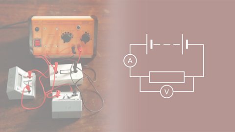
- Ammeters are used to measure the Moving electric charges, eg electrons moving through a metal wire. flowing through components. Voltmeters are used to measure the The potential difference (or voltage) of a supply is a measure of the energy given to the charge carriers in a circuit. Units = volts (V). This is the voltage between two points that makes an electric current flow between them. across components.
Electric circuit symbols
Electrical components, like A device which spins when current flows through it. Motors are used in fans, food processors and many other devices. and A component which produces light when current flows through it. Lamps are commonly known as light bulbs. can be connected together to form a circuit.
A circuit diagram shows how the components are connected.
The following symbols show the different components that can be found in an electrical circuit.
Use straight lines to show the A thin piece of metal which electrical current can flow through. Wires are used to connect components together. Wires are often covered in plastic insulation. Wires are also known as cables or leads. and Circuit symbols are used to represent components when drawing a circuit diagram. to represent each component.
Components
Some of the more common components are:
Switch
A switch used to turn a circuit on (closed) and off (open).
Lamp
An electrical current heats the Direct current is the movement of charge through a conductor in one direction only. in a bulb so that it gives out light.
Fixed resistor
A resistor restricts or limits the flow of electrical current. A An electrical resistor with a fixed value. has a The opposition in an electrical component to the movement of electrical charge through it. Resistance is measured in ohms. that does not change.
Variable resistor
Moving the position of the slider on this resistor, changes the resistance. A A resistor where the value of the resistance can be changed. is used in some dimmer switches and volume controls.
Thermistor
The resistance of a An electrical device whose resistance decreases as its temperature increases. depends on its temperature. At low temperatures, the thermistor has a high resistance. As the temperature increases, the resistance decreases. A thermistor can be used in thermostats or heat activated fire alarms.
Light-dependent resistor (LDR)
The resistance of a LDR depends on light intensity. At low light levels, the LDR has a high resistance. As the light intensity increases, the resistance decreases. A A Light Dependent Resistor is a type of resistor which is affected by changes in light levels. A cadmium sulphide layer causes a decrease in resistance in the light and increase in the dark. can be used as a sensor in cameras or automatic lights that come on when it gets dark.
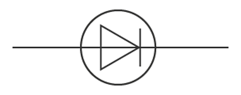
Semiconductor diode
A Insulating material doped with impurities to affect electron energy bands and therefore affect conduction properties.An electrical device that allows current to flow in one direction only. allows current to flow in one direction only. Current will not flow in the other direction. Diodes are used to convert an Also called ac. An electric current that regularly changes its direction and size. into a Direct current is the movement of charge through a conductor in one direction only..
Extended syllabus content: Diodes and light-emitting diodes
If you are studying the Extended syllabus, you will also need to know about diodes and light-emitting diodes. Click 'show more' for this content:
The diode
An electrical device that allows current to flow in one direction only. are electronic components that can be used to regulate the voltage in circuits and to make logic gates. Light-emitting diodes (LEDs) give off light and are often used for indicator lights in electrical equipment such as computers and television sets.
The diode has a very high resistance in one direction. This means that current can only flow in the other direction. Normally a diode will not conduct until a particular voltage is reached.
Series circuits
Video: Explanation of circuits
Jonny Nelson introduces an animated explanation of circuits.
JONNY: Electrical circuits, they're all around us but how do they work?
NARRATOR: Let's look at a simple electrical circuit made up of a power source, a light bulb and a resistor to reduce current flow. The power source drives the charges, in this case, the electrons in the circuit and the electrons transfer energy as they pass through different components. For example, the light bulb where the energy is transferred into light and heat. The current is the rate of flow of charge. In this case, the charge is provided by the electrons, measured in coulombs per second. One amp is equal to one coulomb per second. The potential difference, or PD, is the energy change per unit of charge between two points, measured in volts. One volt is equal to an energy change of one joule per coulomb of charge. If we connect the voltmeter in parallel to the bulb, we can see how many joules of energy each coulomb of charge transfers as it travels through the bulb. It compares before and after the bulb and tells us the difference.
NARRATOR: In our series circuit, the current is constant everywhere. Each charge can only move as fast as the one in front of it. In the same way that all carriages on a train have to move at the same speed, with no one carriage moving faster than any of the others. The potential difference is shared between components because the total energy of each charge from the power source goes into driving the current through all the components. Energy is transferred to each component proportional to is resistance. So if a component has twice the resistance of another, it will receive twice the amount of energy. So twice the potential difference. Also, if we increase the resistance of our circuit by adding another resistor in series, for example, the overall resistance is increased and all the components receive less energy.
NARRATOR: Adding another light bulb in parallel gives the charge another possible route around the circuit and creates a parallel circuit. In a parallel circuit, there are two or more paths for current to flow through. Potential difference is the same across each component of the parallel circuit and the sum of the currents through each path is equal to the total current that flows from the source. If we add a resistor in parallel, it actually decreases resistance because the additional route makes the overall flow easier even though there is another resistor present.
NARRATOR: In parallel circuits, current splits at junctions, similar to a junction on a railway line where some trains go one way and other trains go the other way. This reduces the total number of trains going past on each of the two tracks, splitting the current compared to before the junction. The potential difference is the same on each loop though, because each charge still carries the same amount of energy or to stay with our example, each train still carries the same number of people.
JONNY: Circuits. Turn them on turn them off.
In series circuits, electrical components are connected one after another in a single loop.
Circuit rules
An Subatomic particle, with a negative charge and a negligible mass relative to protons and neutrons. will pass through every component on its way round the circuit. If one of the bulbs is broken then Moving electric charges, eg electrons moving through a metal wire. will not be able to flow round the circuit. If one bulb goes out, they all go out.
Podcast: Series and parallel circuits
Ellie and James explore series and parallel circuits. They also discuss the differences between current and resistance across different circuits and how to calculate them.
JAMES: Hello and welcome to the BBC Bitesize Physics podcast.
ELLIE: The series designed to help you tackle your GCSE in physics and combined science.
JAMES: I’m James Stewart, I’m a climate science expert and TV presenter.
ELLIE: And I’m Ellie Hurer, a bioscience PhD researcher.
JAMES: Just a quick reminder, whilst you're here in the BBC Sounds app, there's also the Bitesize Study Support podcast, which is full of tips and tricks to help you stay focused during revision, and of course, get the best out of your actual exam day.
ELLIE: Right, let's get started.
So, I want you to imagine an electric circuit, the kind of one you probably made for the first time in primary school. It's wires that connect to different electrical components, like a light bulb, a switch, and a battery.
JAMES: Yeah, there are actually two types of circuits. We have series circuits and parallel circuits.
Now in a series circuit, all the electrical components are connected by wires in one loop. So there's only one route for the current to flow. Now electrons pass through all of the components in the circuit in that one loop.
ELLIE: And on the other hand, a parallel circuit has electrical components on separate branches, so the electrons can take different routes around the circuit.
JAMES: And if you want to know exactly what that looks like, be sure to check out the BBC Bitesize website if you are someone that prefers to see rather than hear.
Series circuits and parallel circuits are both used a lot, but they have some really key differences, so let's start with series circuits.
ELLIE: Of course, so there are three key things that you need to know about series circuits. Firstly, in a series circuit, the same current flows through all of the different electrical components.
So the current at all parts of the circuit is the same. Secondly, in a series circuit, the total potential difference of the power supply is shared between all of the electrical components. And finally, the total resistance of all components in a series circuit is the sum of the resistance of each component.
JAMES: And that last point actually might come up in your exam as an equation, so we'll write that out for you. Grab a pen and paper, you can follow us through this one.
The equation to work out the total resistance of multiple components in a series circuit is: resistance total equals the sum of all the individual resistances added together.
ELLIE: For example, a circuit with three components would be R total equals R1 plus R2 plus R3. But one with two components would just be R1 plus R2.
JAMES: Yeah, so a key thing to know is that when you add a component in a series circuit, the total resistance increases because the total resistance is the sum of the resistance of each individual component.
ELLIE: Well, series circuits aren't that common in a regular house. But one great example is fairy lights, which I love.
JAMES: I'm glad we get to talk about fairy lights in the physics podcast. Um, a lot of fairy lights are designed as series circuits. There's one battery or plug, and then the lights are arranged into a circle, so the current flows in one direction.
ELLIE: You can tell that a set of fairy lights is a series circuit. If one bulb blows out, the circuit is broken, so the whole set stops working because the current flows in one loop. We know, it's so annoying, so annoying.
JAMES: But we will try and draw out a series circuit, so if you want to do that with us. Good time to grab your pen and paper.
So we want you to draw out a circuit in the shape of a square with one battery, one switch, and four light bulbs.
ELLIE: Could you say that it's like a mini set of fairy lights?
JAMES: Exactly what I would say it is.
ELLIE: Love it.
JAMES: So, from the information we've shared so far, how could you tell, in your mini fairy light circuit, that the one you're looking at is a series circuit? Have a little think for a moment.
ELLIE: So the key way to tell if a circuit is a series, is that it is one singular loop. There aren't any other branches or directions for the current to flow.
JAMES: Okay, let's move on to parallel circuits. Just like series circuits, there are three key things that you need to know about parallel circuits for your exam.
Number one, in a parallel circuit, the potential difference across each branch of the circuit is the same. In which case, the total potential difference in the battery is the same as the potential difference in each branch. But, in a parallel circuit, the current isn't the same. The total current throughout a parallel circuit is the sum of the current flowing through each of its separate branches.
And finally, in a parallel circuit, the total resistance of two resistors is less than the resistance of the smallest individual resistor.
ELLIE: That feels like a bit of a tongue twister, so let me repeat that.
JAMES: It was.
ELLIE: In a parallel circuit, the total resistance of two resistors is less than the resistance of the smallest individual resistor.
JAMES: And a key thing to know is that when you add other resistors to a parallel circuit, the total resistance decreases because it is less than the resistance of the smallest individual resistor.
ELLIE: And this is because more current is flowing for the same potential difference, which means resistance goes down.
JAMES: And just to note, whilst we're here, when we say resistor, that doesn't just refer to a fixed resistor, for example. All components in the circuit have a resistance. And in an exam question, they might actually ask you to calculate or explain the resistance of something like a lamp.
ELLIE: Right. We know that in a parallel circuit, the current can take different routes around the circuit. So, let's dive into what they look like in a circuit diagram. Okay, we're going to stick with the same example that we used last time, fairy lights, because they're my favourite.
JAMES: Why wouldn't you, yeah?
ELLIE: Exactly. But rather than the kind of fairy lights that completely turn off whenever one bulb breaks, we're going to draw the kind of fairy lights where the set keeps on working, even if one bulb breaks.
ELLIE: So let's try drawing one. Grab your pen and paper. So, I want you to draw a long rectangle circuit with a battery and a light switch on one end. Then, draw four lines connecting the long sides of the rectangle and draw one light bulb on each row.
JAMES: Right, so how can you tell that the circuit you're looking at is a parallel circuit? Have a think for a moment.
The key way to tell if a circuit is a parallel circuit is that there are separate branches to the circuit. So if one lightbulb were to stop working, the current would still be able to flow around the circuit and light up the other lightbulbs.
ELLIE: This means that even if one bulb broke, your fairy lights would still light up.
JAMES: Phew.
ELLIE: Thank goodness.
JAMES: Okay, let's do a quick recap of the three key lessons we've learned today. Firstly, in a series circuit, the current is the same through each component. The potential difference is shared, and the total resistance for all components is the sum of the resistance of each component. Two, the equation to work out the total resistance of all components in a series circuit is: resistance total equals the sum of the resistance of each of the components.
And three, in a parallel circuit, the total current is the sum of the currents through each branch. The potential difference is the same across each branch of the circuit. And the total resistance of all resistors is less than the resistance of the smallest individual resistor.
ELLIE: Thank you, James. And sadly, guys, we're at the end of this episode about series and parallel circuits. However, in the next episode of Bitesize Physics, we're going to be talking all about the domestic uses of electricity and the three pin plug.
JAMES: Thank you for listening to Bitesize Physics.
BOTH: Bye!
Current in series
A A circuit where one component follows directly from another, eg three bulbs in a row with no junctions are said to be connected in series. circuit is one loop; all electrons in that loop form one current. An A device used to measure electric current. will measure the same current wherever it is placed in the circuit:
\(I_{1} = I_{2} = I_{3}\)
This is when:
current (I) is measured in amps (A)
The EMF increases when more sources like cells are added to a series circuit provided they are all connected in the same direction. They are simply added together. So the total EMF of a circuit with two cells each with an EMF of 1.5 V is 3 V.
EMF in series
The current will transfer the capacity for doing work. from the power supply to the components in the circuit. Since energy has to be conserved, all of the source energy is shared between the components. Since The potential difference (or voltage) of a supply is a measure of the energy given to the charge carriers in a circuit. Units = volts (V). This is the voltage between two points that makes an electric current flow between them. is used to measure changes in energy, the potential difference supplied is equal to the total of the potential differences across all other components:
\(V_{s} = V_{1} + V_{2}\)
This is when:
potential difference (V) is measured in volts (V)
Resistance in series
If An electrical component that restricts the flow of electrical charge. Fixed-value resistors do not change their resistance, but with variable resistors it is possible to vary the resistance. are connected in series, the current must flow through both of them meaning the resistances are added together:
\( R_{total} = R_{1} + R_{2}\)
This is when:
resistance - R - is measured in ohms - Ω
Key fact
In series circuits:
- current is the same through each component
- the total potential difference of the power supply is shared between the components
- the total resistance of the circuit is the sum of individual resistors
Parallel circuits
In parallel circuits, electrical components are connected alongside one another, forming extra loops.
Circuit rules
An electron will not pass through every component on its way round the circuit. If one of the bulbs is broken then current will still be able to flow round the circuit through the other loop. If one bulb goes out, the other will stay on.
Current in parallel
Since there are different loops, the current will split as it leaves the cell and pass through one or other of the loops. An ammeter placed in different parts of the circuit will show how the current splits:
\(I_{1} = I_{2}+I_{4} = I_{3}\)
This is when:
current (I) is measured in amps (A)
Extended syllabus content: Current in parallel
If you are studying the Extended syllabus, you will also need to know about the sum of the currents in a junction. Click 'show more' for this content:
The sum of the currents into a junction is the same as the sum of the currents out of the junction.
Potential difference in parallel circuits
Since energy has to be conserved, the energy transferred around the circuit by the electrons is the same whichever path the electrons follow. Since potential difference is used to measure changes in energy, the The potential difference (or voltage) of a supply is a measure of the energy given to the charge carriers in a circuit. Units = volts (V). This is the voltage between two points that makes an electric current flow between them. supplied is equal to the potential differences across each of the parallel components:
\(V_{s} = V_{1} = V_{2}\)
This is when:
potential difference (V) is measured in volts (V)
Resistance in parallel circuits
If An electrical component that restricts the flow of electrical charge. Fixed-value resistors do not change their resistance, but with variable resistors it is possible to vary the resistance. are connected in parallel the supply current is divided between them. The overall resistance is reduced as the current may follow multiple paths.
Key facts
In parallel circuits:
- the total current supplied is split between the components on different loops
- potential difference is the same across each loop
- the total resistance of the circuit is reduced as the current can follow multiple paths
Extended syllabus content: Resistance in parallel
If you are studying the Extended syllabus, you will also need to be able to calculate the combined resistance of two resistors in parallel . Click 'show more' for this content:
The total resistance of two resistors in parallel can be calculated by:
\((\frac{1}{R}=\frac{1}{R_1}+\frac{1}{R_2})\)
If more resistors are present they can be added to the right of the formula.
Action and use of circuit components
As the potential difference across an electrical conductor like a metal wire increases so does its resistance if the current remains the same.
A potential divider does exactly as its name suggests - it divides a supply voltage across two An electrical component that restricts the flow of electrical charge. Fixed-value resistors do not change their resistance, but with variable resistors it is possible to vary the resistance. which are connected in series.
The two resistors may have fixed values or one may be an LDR, a thermistor or other input device.
The supply voltage is divided in the ratio of the resistances in the potential divider.
Extended syllabus content: Variable potential dividers
If you are studying the Extended syllabus, you will also need to know about variable potential dividers and the equation for two resistors used as a potential divider. Click 'show more' for this content:
A potential divider does exactly as its name suggests - it divides a supply voltage across two An electrical component that restricts the flow of electrical charge. Fixed-value resistors do not change their resistance, but with variable resistors it is possible to vary the resistance. which are connected in series.
The two resistors may have fixed values or one may be an LDR, a thermistor or other input device.
The supply voltage is divided in the ratio of the resistances in the potential divider.
For the potential divider shown:
\(\frac{{{V_1}}}{{{V_2}}} = \frac{{{R_1}}}{{{R_2}}}\)
\({V_s} = {V_1} + {V_2}\)
\({V_1} = {V_s} \times \frac{{{R_1}}}{{{R_1} + {R_2}}}\)
Of the three relationships stated above, any one can be used to find the voltage across a given resistor.
If one of the resistances in a voltage divider increases, then the voltage across that resistor also increases. This may appear to be the wrong way round but it is because of the way the resistors are connected together.
The circuit of a voltage divider may be drawn with the two resistors vertical, not horizontal. If there are two resistors in series across a voltage source, then the circuit is a voltage divider.
Question
What is the total resistance of a 3 Ω resistor and a 6 Ω resistor in parallel?
\([\frac{1}{R_{\text{total}}} = \frac{1}{R_1} + \frac{1}{R_2}]\)
\([\frac{1}{R_{\text{total}}} = \frac{1}{3} + \frac{1}{6}]\)
\([\frac{1}{R_{\text{total}}} = \frac{1}{2}]\)
\([R_{\text{total}} = 2 \div 1 = 2 \ \Omega]\)
Quiz
Test your knowledge of electric circuits with this quiz.
More on Electricity and magnetism
Find out more by working through a topic
- count4 of 7
- count5 of 7
- count6 of 7

- count7 of 7