What are the key learning points about the AC generator?
An electric current can be induced in in a coil of wire by moving a magnet in and out of the coil.
The size of the induced current is increased by increasing the speed of the moving magnet, using a stronger magnet or by having more turns on the coil of wire.
The direction of the induced current is reversed by changing the direction of the moving magnet or by reversing the poles of the magnet.
AC generators are used in the generation of electricity and in their simplest form consist of a coil of wire rotated between the poles of a magnet.
What is electromagnetic induction?
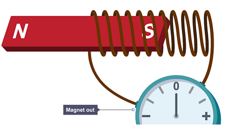
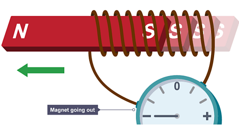
When one of the Either of the two points of a magnet to and from which the lines of magnetic force are directed. of a permanent magnet is moving into, or out of, a coil of wire connected to a sensitive centre-zero A device used to measure electric current., the pointer on the ammeter deflects to one side.
This indicates that a current is being induced in the coil.
This electromagnetic induction can be demonstrated using the apparatus shown below:
1 of 4
The direction of the induced current is reversed when the magnet is moved out of the coil again.
It can also be reversed if the other pole of the magnet is moved into the coil.
A current can also be induced if:
The magnet is held stationary and the coil is moved.
Or the magnet is rotated close to the coil.
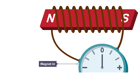
Notice that no current is induced when the magnet is not moving, even if it is inside the coil.
If the magnet and the coil are held together and both are moved together no current is induced.
We say that a current is induced when the magnet moves relative to the coil.
Key points
A current is induced in a wire when it moves relative to a magnet.
The direction of the current can be reversed by reversing the direction the magnet moves or by turning the magnet around and reversing the direction of the magnetic field.
Summary of observations
| Direction of movement of magnet | Needle of ammeter | Current is induced? Yes or No |
|---|---|---|
| Magnet is stationary outside of coil | Remains at zero | No |
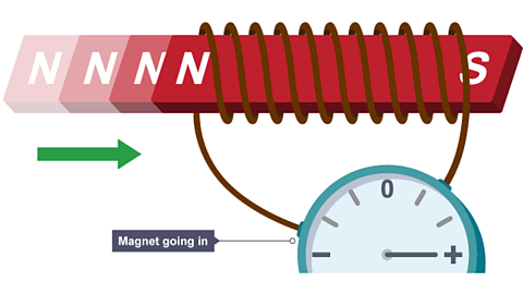
| South pole moves into coil | Deflects in one direction and then returns to zero | Yes, while the magnet is moving |
| Magnet is stationary inside of coil | Remains at zero | No |
| South pole moves out of coil | Deflects in the opposite direction and then returns to zero | Yes, while the magnet is moving |
Key points
The size of the induced current can be increased by:
Moving the magnet faster into and out of the coil.
Adding more turns to the coil.
Increasing the strength of the magnet.
The current induced when a magnet moves into and out of a coil is an alternating current.
The process is the basis of electricity generation in power stations and generators.
Worked example
Question
The north pole of a magnet is moved into a coil connected to a centre-zero A device used to measure electric current..
The needle deflects to the right.
- Complete the results table to show the deflection, if any, of the ammeter needle.
| Movement of magnet | Deflection of needle |
|---|---|
| North pole moves towards coil | Right, and then returns to zero |
| Magnet at rest inside coil | |
| North pole moves away from coil | |
| South pole moves towards coil | |
| South pole moves away from coil |
In terms of the electric current what is the difference between a deflection of the ammeter to the right and to the left?
List three things that could be done to make the induced current, and hence the deflection of the ammeter, bigger.
Answer
- The completed table:
| Movement of magnet | Deflection of needle |
|---|---|
| North pole moves towards coil | Right, and then returns to zero |
| Magnet at rest inside coil | No deflection |
| North pole moves away from coil | Left, and then returns to zero |
| South pole moves towards coil | Left, and then returns to zero |
| South pole moves away from coil | Right, and then returns to zero |
- A deflection of the ammeter to the right and to the left indicates the current changing direction.
When the needle deflects to the right, the current flows in one direction.
When the needle deflects to the left, the current flows in the opposite direction.
- The induced current, and hence the deflection of the ammeter, could be made bigger by:
Moving the magnet faster.
Using a stronger magnet.
Having more turns of wire in the coil.
How do AC generators work?
Cars use a type of AC generator, called an An electrical generator which produces alternating current, an ac generator., to keep the battery charged and to run the electrical system while the engine is working.
The diagram shows a simple AC generator.
Slip rings maintain constant contact with the same sides of the coil
As one side of the coil moves up through the A region around a magnet or around a wire carrying a current, where a magnetic force is experienced., a current is induced in one direction.
As the rotation continues and that side of the coil moves down, the The production of a potential difference (voltage) when a conductor, such as a wire, is moved through a magnetic field or exposed to a varying magnetic field. If the conductor is part of an electric circuit, an induced current will flow. current reverses direction.
This means that the generator produces a current that is constantly changing.
This is alternating current or AC.
The size of the induced voltage, and hence induced current, can be increased by:
Increasing the speed of rotation of the coil.
Increasing the strength of the magnetic field by using a stronger magnet.
Increasing the number of turns on the coil.
In Northern Ireland, large scale AC generators are used to produce electricity, like the ones at Ballylumford and Kilroot in Co. Antrim, which is then transmitted across country to consumers.
The coil of these generators rotates 50 times a second and that is why our mains supply is 50 Hz AC.
What does an alternator output look like on a graph?
The output of a generator can be represented on an induced current–time graph which is shown below.
It shows four different positions of the coil of the generator and the corresponding induced current.
The current-time graph for an alternator
A - The coil is at 0°. The coil is moving parallel to the direction of the magnetic field, so no current is induced.
B - The coil is at 90°. The coil is moving at 90° to the direction of the magnetic field, so the induced current is at its maximum.
C - The coil is at 180°. The coil is moving parallel to the direction of the magnetic field, so no current is induced.
D - The coil is at 270°. The coil is moving at 90° to the direction of the magnetic field, so the induced The potential difference (or voltage) of a supply is a measure of the energy given to the charge carriers in a circuit. The unit this is measured with is volts (V). is at its maximum. Here, the induced current is in the opposite direction to what it was at B.
E - The coil is at 360°, i.e it is back at its starting point, having done a full rotation. The coil is moving parallel to the direction of the magnetic field, so no current is induced.
What is mutual induction?
The production of a potential difference (voltage) when a conductor, such as a wire, is moved through a magnetic field or exposed to a varying magnetic field. If the conductor is part of an electric circuit, an induced current will flow. can occur in a coil when the current in a neighbouring coil changes.
This is called mutual induction and is the principle behind An electrical device that increases, or decreases, the potential difference (voltage) of an alternating current., which are used to change the size of an AC voltage in many household appliances.
Mutual induction can be demonstrated using the apparatus shown below.
Two coils of wire are placed beside each other.
One is connected to a power supply and switch.
This is called the primary coil.
The neighbouring coil is connected to a sensitive, centre-zero meter.
This is called the secondary coil.
The power supply is switched off, but set to 3 V.
An iron core links the two coils but there is no electrical connection between them.
They are linked magnetically by the iron core, but not electrically.
What can be observed?
When the power supply is switched on, the needle on the A device used to measure electric current. flicks in one direction, and then returns to zero.
If the switch remains closed, the needle of the ammeter remains at zero.
When the power supply is switched off, the needle on the ammeter flicks in the other direction and then returns to zero.
If the switch remains open, the needle of the ammeter remains at zero.
The primary coil is simply an electromagnet connected to a Direct current is the movement of charge through a conductor in one direction only..
When the switch is closed, its magnetic field strength increases from zero to its maximum steady value. This changing magnetic field links with the secondary coil. The secondary coil is then a conductor in a changing magnetic field. Hence, a current is induced in the secondary coil and the needle on the ammeter flicks to one side. This is called mutual induction.
The current is only induced when the magnetic field of the primary coil is changing. As soon as the magnetic field is at full strength it stops changing, current is no longer induced in the secondary, and the needle of the ammeter returns to zero.
The needle of the ammeter will remain at zero until the current in the primary, and hence its magnetic field, changes again.
When the switch is opened, the reverse happens. Current in the primary coil falls to zero, which causes its magnetic field to collapse from its maximum value to zero. This changing (decreasing) magnetic field links with the secondary coil and induces a current to flow in it in the opposite direction. The needle on the ammeter flicks to the other side.
As soon as the magnetic field is at zero it stops changing, current is no longer induced in the secondary coil, and the needle of the ammeter returns to zero.
If the switch is left open, no current is induced in the secondary coil. There is no current in the primary coil and hence no changing magnetic field to link the secondary coil.
If the switch remains closed, no current is induced in the secondary coil. The magnetic field of the primary coil is not changing and so current is not induced in the secondary coil.
The purpose of the soft iron core is to connect the coils magnetically. The core lets the changing magnetic field of the primary easily, and efficiently, link with the secondary coil.
The DC supply and switch can be replaced by an AC supply. When the AC supply is switched on the needle of the ammeter moves from side to side repeatedly.
Key facts
A changing magnetic field in the primary coil, links with the secondary coil, and induces a current to flow in the secondary coil.
This principle is the basis of how a An electrical device that increases, or decreases, the potential difference (voltage) of an alternating current.changes the size of an AC current or voltage.
Worked example
Question
What happens to the pointer on the sensitive ammeter when:
The switch is closed and kept closed?
The switch is opened and left opened?
Explain your answers to 1. and 2.
Answer
The needle flicks to the right, and then returns to zero where it remains.
The needle flicks to the left, and then returns to zero where it remains.
When the switch is closed the current grows to a maximum from zero and there is a changing magnetic field in the primary coil.
This links the secondary coil and induces a current to flow.
The induced current stops when the magnetic field stops changing (i.e. when it has reached full strength), and the needle returns to zero.
It remains there until the magnetic field changes again.
When the switch is opened the current falls to zero and there is a changing magnetic field again in the primary coil.
This links the secondary coil and induces a current to flow – in the opposite direction.
The induced current stops when the magnetic field stops changing (i.e. when it has reached zero), and the needle returns to zero.
Test your knowledge
More on Unit 2: Magnetism and electromagnetism
Find out more by working through a topic
- count4 of 4
- count1 of 4

- count2 of 4