What are the key points about the reflection and refraction of light?
Reflection of light.
The The law of reflection states that the angle of reflection is equal to the angle of incidence or i=r..
Properties of the image in a A mirror with a flat, smooth, reflective surface..
Process by which a wave changes speed and sometimes direction upon entering a denser or less dense medium, eg a light ray changes direction when refracted by a lens. of light.
Measuring angles of and The angle between the normal and the refracted ray..
Dispersion of light in a A block of glass or other transparent material that disperses light to form a spectrum..
What is a ray diagram?
A ray diagram shows how light travels, including what happens when it reaches a surface.
In a ray diagram, you draw each ray as:
a straight line,
with an arrowhead pointing in the direction that the light travels.
When measuring angles:
it is always the angle between the ray and the normal that is measured,
a protractor is used.
Remember to use a ruler and a sharp pencil.
The diagram below shows reflection in a plane mirror.
How to investigate the law of reflection
On a sheet of white paper draw a pencil line – label this AB.
Using a protractor, draw a A construction line drawn at 90° to the surface. at C, roughly the middle of AB.
Draw a line at 20° to the normal.
Position a plane mirror carefully along AB.
Direct a ray of light from a ray box along the 20° line – this is the Light ray moving towards a surface or boundary..
Record the i in a suitable table.
Use 2 pencil Xs to mark the position of the reflected ray.
Take away the mirror and join these Xs back to C. This is the reflected ray. Put an arrow on it to show its direction.
Measure the angle between the normal and the reflected ray with the protractor and record the The angle between the reflected ray and the normal. r in the table.
Repeat the experiment for a series of incident rays.
Results
| Angle of incidence i /o | Angle of reflection r /o |
|---|---|
| 20 | |
| 30 | |
| 40 | |
| 50 | |
| 60 | |
| 70 | |
| 80 |
Conclusion
When light is reflected by a A mirror with a flat, smooth, reflective surface.:
The angle of incidence = the angle of reflection.
This is known as the law of reflection.
Key fact
The law of reflection for a plane mirror: angle of incidence i = the angle of reflection r.
What is the law of reflection?
The law of reflection states that: angle of incidence i = angle of reflection r.
For example, if a light ray hits a surface with an angle of incidence of 45°, it will be reflected with an angle of reflection of 45°.
How to investigate the position of an image in a plane mirror
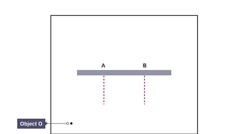
Image caption, Step 1. Draw a pencil line across the top of a sheet of white paper. Mark points A and B. Select a position for the object and label that O.
1 of 2
Draw a pencil line across the top of a sheet of white paper. Mark points A and B. Select a position for the object and label that O.
Use a pencil and ruler to draw an Light ray moving towards a surface or boundary. from O to A and from O to B. Include arrows.
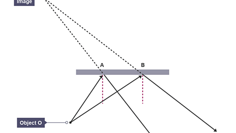
Use a ray box to direct two rays of light along the lines from object O towards points A and B.
Mark 2 pencil Xs to mark each of the reflected rays from A and from B.
Remove the mirror and use a pencil and ruler to join the Xs These represent the reflected rays.
Extend the reflected rays behind the mirror until they meet at point. This is where the image was formed. Label the point I. These dotted lines are called virtual rays.
With a 30 cm ruler, measure the If the angle between two lines is a right angle, the lines are said to be perpendicular. distance from O to the mirror and from I to the mirror.
Repeat the experiment for different positions of the object O.
Conclusion
For each position of the object:
- the perpendicular distance of the object O from the mirror equals the perpendicular distance of the image I from the mirror.
Another way of saying this is:
- the image is the same distance behind the mirror as the object is in front.
What are the properties of the image in a plane mirror?
The image in a mirror is:
upright – but left and right are reversed. The image is laterally inverted.
the same height as the object.
as far behind the mirror as the object is in front.
virtual.
A real image is an image that can be projected onto a screen.
A virtual image is an image from which rays of light appear to diverge, and do not actually pass through.
The image appears to be behind the mirror.
A virtual image cannot be formed on a screen.
It can only be seen by looking into the mirror.
Key point
The image in a A mirror with a flat, smooth, reflective surface. is:
as far behind the mirror as the object is in front.
upright but laterally inverted.
same size as the object.
virtual.
Question
What is the angle of reflection from the second mirror?
- The angle of incidence at mirror A = 70o.
- i = r and so the angle of reflection at mirror A = 70o.
- The angle between the reflected ray and the mirror = 20o. The angle of incidence at mirror B is an alternate angle and so also equals 20o.
- i = r and so the angle of reflection at mirror B = 20o.
What is the refraction of light?
When light travels from air into glass it slows down because glass is more (optically) dense than air.
This change in speed can cause the light to change direction at the boundary between the two transparent materials.
This change in direction of a beam of light as it travels from one material to another is called refraction.
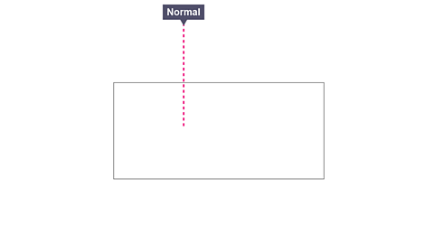
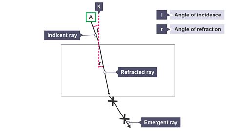
The normal is a construction line drawn at right angles to the surface of the glass block.
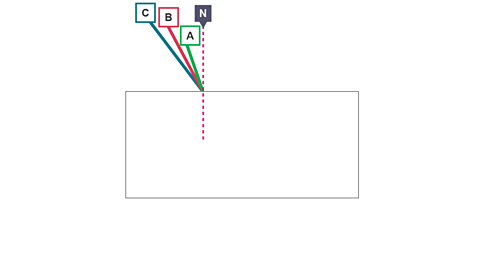
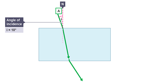
Angle of incidence i = angle between the incident ray and the normal.
Angle of refraction r = angle between the refracted ray and the normal.
Key fact
Angles of incidence and refraction are always measured between the normal and the corresponding ray of light.
Direction of refraction
Glass is denser than air, so when light passes from air into glass it slows down.
If the ray meets the boundary at an angle to the normal, it refracts towards the normal.
Light speeds up as it passes from glass into air because air is less dense than glass.
If the ray meets the boundary at an angle to the normal, it refracts away from the normal.
The greater the change of speed of light at a boundary, the greater the amount of refraction.
Light is refracted more by glass than by water because glass is denser than water and so slows it down more.
Key facts
When light travels from a less dense to a more dense material, it gets slower and refracts towards the A construction line drawn at 90° to the surface.. e.g. air to glass.
When light travels from a more dense to a less dense material, it gets faster and refracts away from the normal. e.g. glass to air.
The greater the change of speed, the more the light is refracted.
One way of remembering this is to use the word FAST.
If light gets Faster it refracts Away from the normal.
If light gets Slower it refracts Towards the normal.
| Letter | Meaning |
|---|---|
| F | Faster |
| A | Away |
| S | Slower |
| T | Towards |
If light is Light ray moving towards a surface or boundary. along the normal when it passes from air into glass it still slows down but its direction does not change – it passes straight through.
Likewise, if light is incident along the normal when it passes from glass into air it still speeds up but its direction does not change – it passes straight through.
A ray of light incident along the normal passes straight through without being refracted.
Prescribed practical P6: Refraction of light
A guide to carrying out a practical investigating angles of incidence and refraction
What is the purpose of prescribed practical P6?
To use ray tracing to measure the and The angle between the normal and the refracted ray. when light is refracted by a glass block.
To demonstrate understanding that the angles of incidence and refraction are measured from a line at right angles to the glass surface known as the A construction line drawn at 90° to the surface..
And to use the measurements taken to plot a graph of angle of incidence against angle of refraction to show that they are related but notWhen one variable is zero so is the other. As one variable increases the other does at the same rate. When 𝒚 is plotted against 𝒙 this produces a straight-line graph through the origin..
There are different ways to investigate refraction in rectangular blocks.
In this required practical activity, it is important to:
make, measure and record the angles of incidence accurately using a protractor.
observe and use a protractor to measure angles of refraction.
What are the variables?
In this experiment:
Independent variable is the angle of incidence.
Dependent variable is the angle of refraction.
Control variables are the material of the block, the shape of the block and the colour of the light.
Remember - these variables are controlled (or kept the same) because to make it a fair test, only 1 variable can be changed, which in this case is the angle of incidence.
What is the prediction?
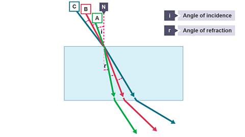
Light is travelling from air to glass and so is refracted towards the normal.
However, as the angle of incidence increases the refracted light will bend from a bigger initial angle, and so the angle of refraction will also be bigger.
What apparatus is used in this practical?
Low voltage power pack, a 12V ray box, a single slit comb, a rectangular glass block, a sheet of white paper, a protractor, a sharp pencil.
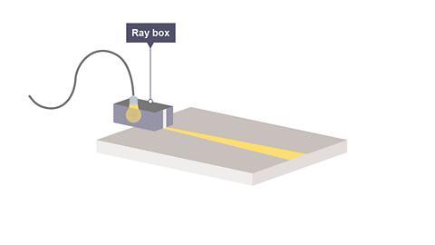
Image caption, 1. Set up the ray box and slit so that a narrow, bright ray of light is produced.
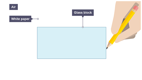
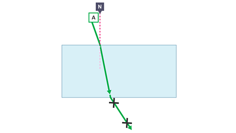
1 of 9
Possible error
The main cause of error in this experiment is the measurement of the angles of incidence and refraction.
This can be kept to a minimum by:
replacing the block carefully on its outline.
ensuring that the power pack is set to 12 V, so that the ray box is at maximum brightness.
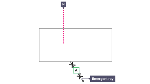
doing the experiment in a dark room so that the emergent ray can be easily seen and marked.
Results
| Angle of incidence i /o | Angle of reflection r /o |
|---|---|
| 10 | |
| 20 | |
| 30 | |
| 40 | |
| 50 | |
| 60 | |
| 70 |
Graph
Plot a graph of angle of incidence, i in ° on the y-axis against angle of refraction, r in ° on the x-axis and draw the line of best fit.
What conclusion can be drawn from prescribed practical P6?
Conclusion
We can see from the graph that as the angle of incidence, i, increases, the angle of refraction, r, also increases.
This agrees with our prediction.
However, the angle of incidence is not When one variable is zero so is the other. As one variable increases the other does at the same rate. When 𝒚 is plotted against 𝒙 this produces a straight-line graph through the origin. to the and angle of refraction as the line of best fit is not a straight line through the origin.
The conclusion is the angles are related but not proportional.
What is refraction by a prism?
The Light ray moving towards a surface or boundary. is refracted towards the A construction line drawn at 90° to the surface. as it enters the glass prism from air.
It is then refracted away from the normal at the boundary between glass and air as it leaves the prism.
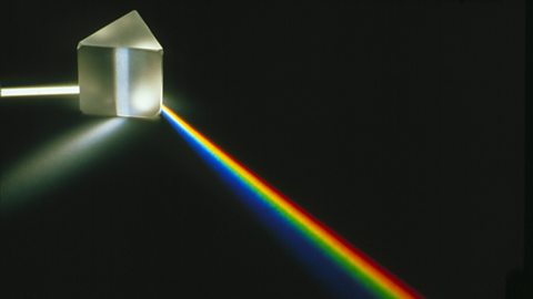
What is the dispersion of white light?
White light can be split up to form a Refers to the visible spectrum, the range of the electromagnetic spectrum visible to the human eye. It can be seen when white light is split by a prism, or by raindrops to form a rainbow. using a A block of glass or other transparent material that disperses light to form a spectrum.
Light waves are Process by which a wave changes speed and sometimes direction upon entering a denser or less dense medium, eg a light ray changes direction when refracted by a lens. as they enter the glass because they are slowed down.
The spectrum is produced because different colours of light travel at different speeds in glass.
Red light is slowed down least by glass and is refracted least.
Violet light is slowed down most by glass and is refracted most.
As a result, the coloured light spreads out to form a spectrum of white light.
This is called dispersion.
Key points
The spectrum of white light is produced because different colours of light travel at different speeds in glass:
Red light is slowed down least by glass and is refracted least.
Violet light is slowed down most by glass and is refracted most.
White light can be split up into the seven colours of the visible spectrum.
There is an easy way to remember the order of the colours of white light by using a sentence: Richard Of York Gave Battle In Vain.
Red, Orange, Yellow, Green, Blue, Indigo, Violet.
How much do you know about the reflection and refraction of light?
More on Unit 2: Light
Find out more by working through a topic
- count3 of 3