For many years mystery has surrounded the construction of the Iron Bridge in Shropshire. Recent discoveries, as David de Haan explains, may shed light on the origins of an engineering wonder.
By David de Haan
Last updated 2011-02-17
For many years mystery has surrounded the construction of the Iron Bridge in Shropshire. Recent discoveries, as David de Haan explains, may shed light on the origins of an engineering wonder.
Despite its pioneering technology in 1779, as the first structural use of cast iron, no eye witness accounts are known which describe the Iron Bridge being erected. However, recent discoveries, research and experiments have shed new light on the mystery of exactly how it was built, challenging the assumptions of recent decades. In 1997 a small watercolour sketch by Elias Martin came to light in Stockholm. Although there are a wealth of early views of the Bridge by numerous artists, this is the only one which actually shows it under construction.
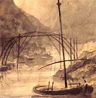 A watercolour of the Iron Bridge under construction in 1779, by Elias Martin. © In October 2001 a half-size model was built to reproduce the watercolour and test its credibility as an engineering solution. Meanwhile, a detailed archaeological, historical and photographic survey was done by the Ironbridge Gorge Museum Trust, along with a 3D CAD (computer-aided design) model by English Heritage.
The results of these discoveries and experiments tell us a lot more about how the Bridge was built. We now know that all the large castings were made individually as they are all slightly different. The joints would all be familiar to a carpenter - mortise and tenons, dovetails and wedges - but this was the traditional way in which iron structures were joined at the time.
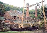 Stage 1: The building of the half-scale model begins. The derrick poles and brace lift a rib from a barge. © In 2001, a half-scale model of the main section of the Bridge was reconstructed as part of an experiment. Armed with old ledger entries and 18th century lifting manuals, advice from a range of experts and a recently discovered painting of the Iron Bridge under construction, the engineer Jamie Hillier and a labour force provided by the Royal Engineers built the model using only 18th century techniques.
As a result of the reconstruction, it is now believed that the Bridge was built in the following stages:
Stone footings were built using local sandstone, and topped by iron base plates. The rest of the massive abutments were not built at this stage. A pair of 21m (70ft) wooden derrick poles were stood in the river bed, which acted as cranes. They were angled slightly towards the middle of the river and were stiffened near the top by a horizontal timber brace which provided further lifting points. The whole arrangement could be lent over in either direction, upstream or downstream, to reach different positions. Castings were brought to the site by boat, probably having been cast at Bedlam Furnaces located on the north bank of the Severn just 500m downstream.
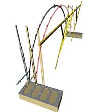
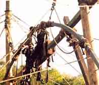 During the building of the half-scale model, two half ribs were joined at the crown to complete the first of five arches. © The arch has five parallel iron frames, built starting with the upstream one and working back towards the centre. The first pair of Inner Verticals was slotted into the base plate, one on either bank. A Lower Rib was lifted from a barge until its bottom end sat on the southern base plate and rested against the Inner Vertical. The top end was raised to the correct height, and the same process was repeated from the other bank until the two halves lined up.
The two arcs were joined at the Crown by a sophisticated scarf joint, which was secured by three large nuts and bolts. Balancing on a slender timber brace, this was a job for men with steady nerves and no fear of heights. Ropes stopped the castings tipping over at this delicate stage. According to a newspaper report, the first arch spanned the River Severn on 2nd July 1779.
Stage 3
 Stage 3: The three upstream arches are erected. © Using the same scaffold frame but leaning it over slightly less each time, two more arches were completed in the same way. Temporary timber braces made the structure rigid, and these were later replaced by iron castings.
Stage 4
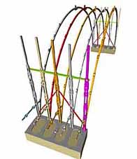 Stage 4: The lower ribs of all five frames are erected, with bracing added to the Inner Verticals to make the structure more rigid. © The derrick poles were next lent in the downstream direction allowing the remaining two ribs to be erected, starting with the one furthest away. All five frames were then braced by diagonal and horizontal castings, which straddled the uprights. The arches and the uprights were also tied together near the base plates by short horizontal braces. With all five Lower Rib arches in place, the ironwork was free-standing and strong enough to be used as a scaffold for lifting lighter castings. There were still no abutments at this point.
Stage 5
The rest of the middle frame was built next, starting with the Middle Ribs, followed by the Outer Verticals, then the Outer Ribs, all held the correct distance apart by a series of decorative radial castings. Finally the decorative Circles and Ogees were added at the upper levels. The abutments were built up to their final height behind the Outer Vertical during this process. The scaffold was dismantled and the derricks re-sited so the same sequence could be repeated for the remaining frames.
The Deck Bearers were brought in at high level from the now completed abutment on the north bank, probably having been cast in a temporary furnace in The Square next to the Bridge. Each one was different and made to measure. Each pair of straight Deck Bearers was linked at the centre by a 5m long curved casting, the Crown Bearer, which gripped and tightened the Crown Joint. All the joints on the Bridge were then packed with iron blocks and wedges, which were sealed in with lead.
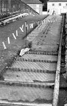 Stage 7: The cast iron deck plates and their locating wedges were revealed in 1975 while laying a new road surface. © Deck plates were probably cast in The Square and levered into place, starting with the centre one. They were located along the Deck Bearers by cast iron wedges and were topped by a road surface of clay and blast furnace slag.
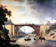 Abraham Darby commissioned this painting by William Williams in 1780 to promote the Bridge. © There are 482 main castings, but with the deck facings and railings the number rises to 1,736. There were no injuries during the construction process, which took three months during the summer of 1779, although work on the approach roads continued for another two years. The Bridge was opened to traffic on 1st January 1781. Abraham Darby III promoted the Bridge by commissioning paintings and engravings, but he had lost a lot of money on the project, which had cost nearly double the estimate.
Movement in the south abutment was severe and it had to be demolished in 1802 and replaced by two timber side arches, which in turn were replaced in cast iron in 1821 and remain to this day. In 1934 the Bridge was closed to vehicles and scheduled as an ancient monument, but pedestrian tolls continued until 1950.
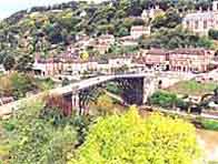
Universally recognised as the symbol of the Industrial Revolution, the Iron Bridge stands at the heart of the Ironbridge Gorge World Heritage Site.
Books
The Iron Bridge by Sir Neil Cossons and Barrie Trinder (Ironbridge Gorge Museum Trust and Moonraker Press, 1979) A revised edition is due out in March 2002.
The Iron Bridge and the Town a site guide (Ironbridge Gorge Museum Trust, 1995)
David de Haan is deputy director of the Ironbridge Gorge Museum Trust, and programme director of the Ironbridge Institute. He worked at the Science Museum in London from 1970-78 and is a Fellow of the Museums Association and Member of the Newcomen Society.


BBC © 2014The BBC is not responsible for the content of external sites. Read more.
This page is best viewed in an up-to-date web browser with style sheets (CSS) enabled. While you will be able to view the content of this page in your current browser, you will not be able to get the full visual experience. Please consider upgrading your browser software or enabling style sheets (CSS) if you are able to do so.
